Triumph T140 engine rebuild

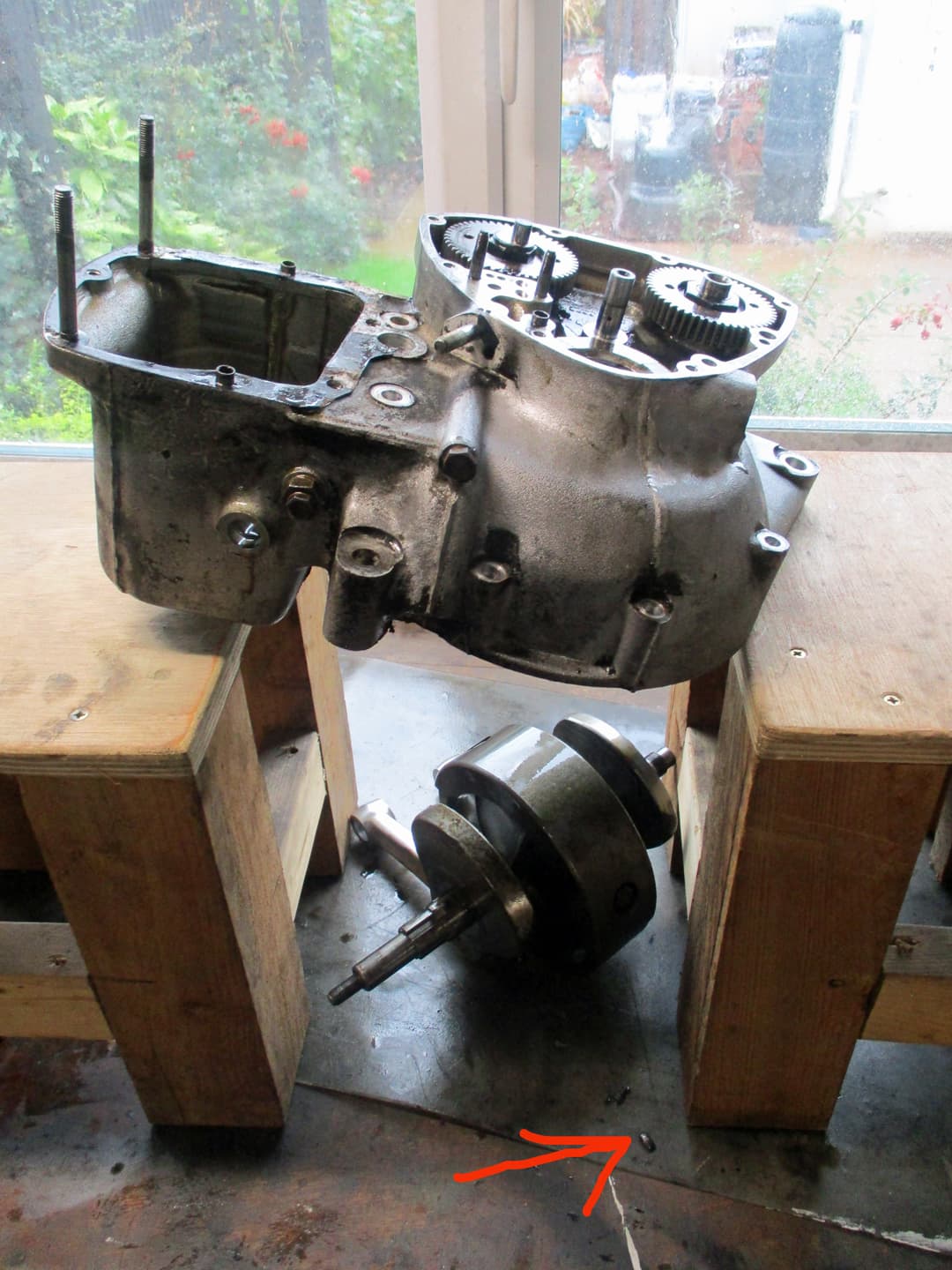
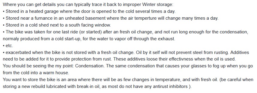
This is a 1978 T140V engine, just removed from a complete bike that is undergoing a bit of a makeover.
These bikes are passing through their 50 years of age. They were the hooligans choice in the 80s as those with deeper pockets moved across to the electric start, faster Kawi Z900s and the hairy two stroke triples with expansion chambers.
The Bonnies left behind were accosted by teenagers with only a hammer and a pair of pliers to keep them going. A lot have been left in a shed or garage for decades. A fair few have been shipped back to their homeland from abroad.
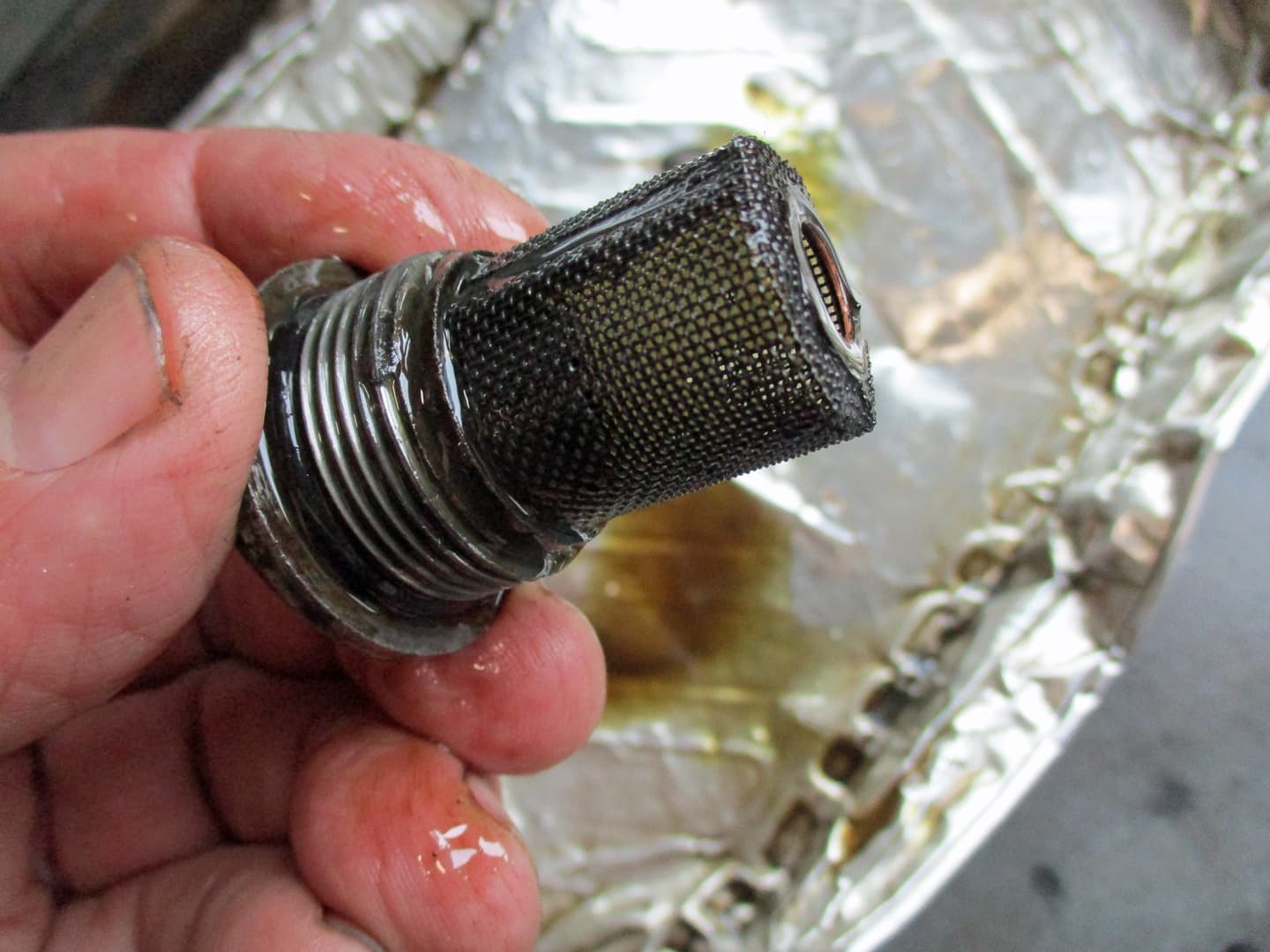
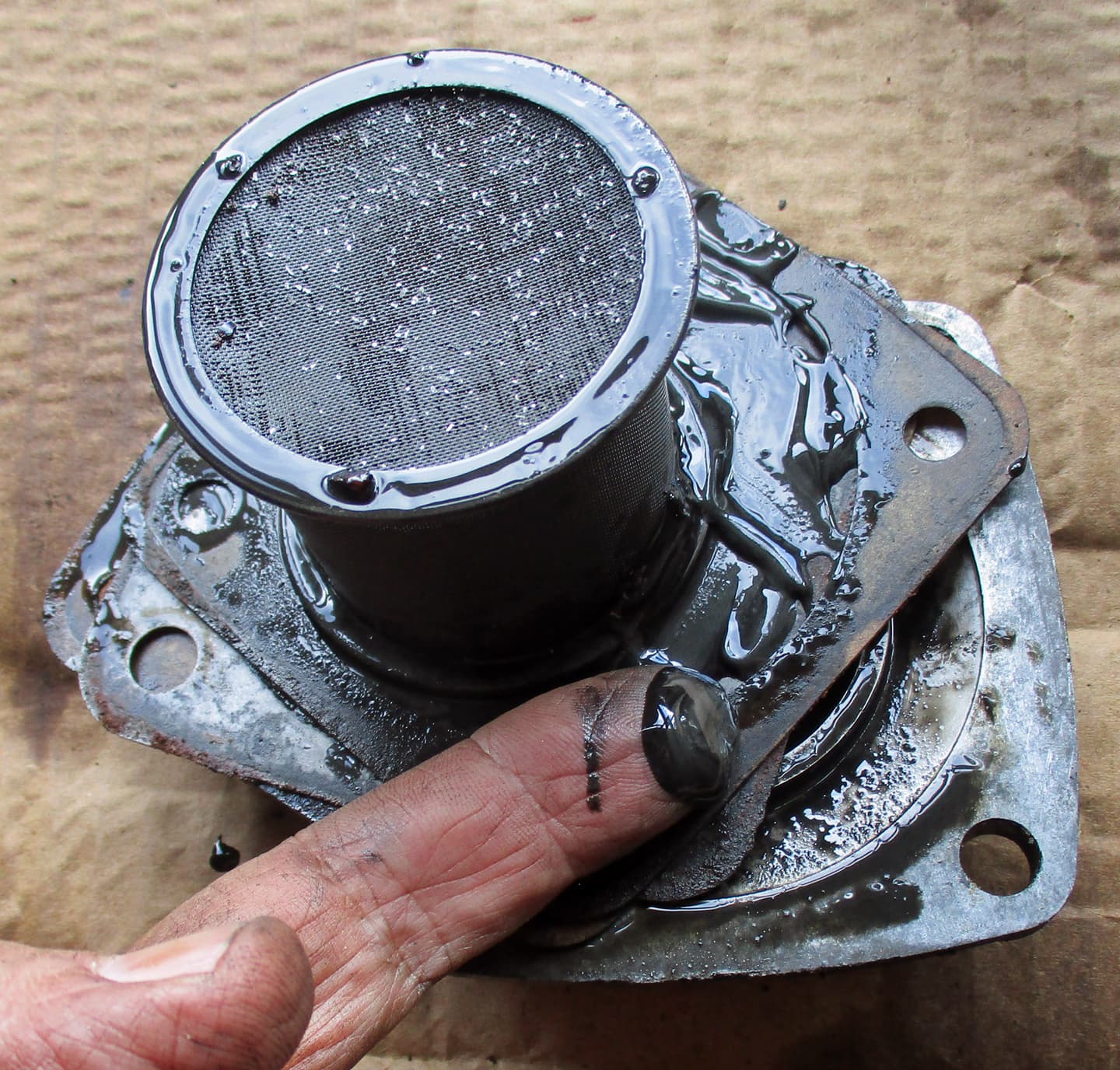
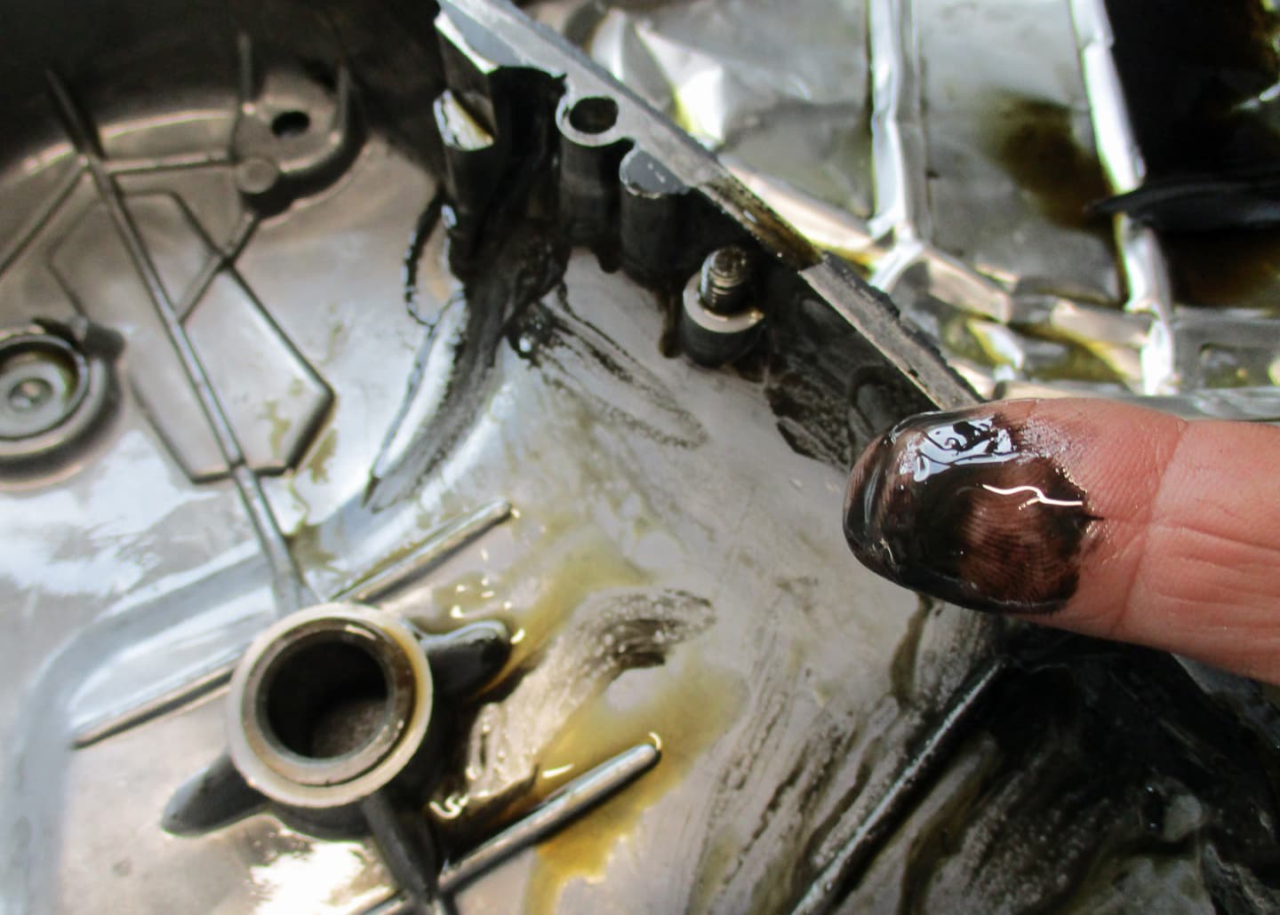
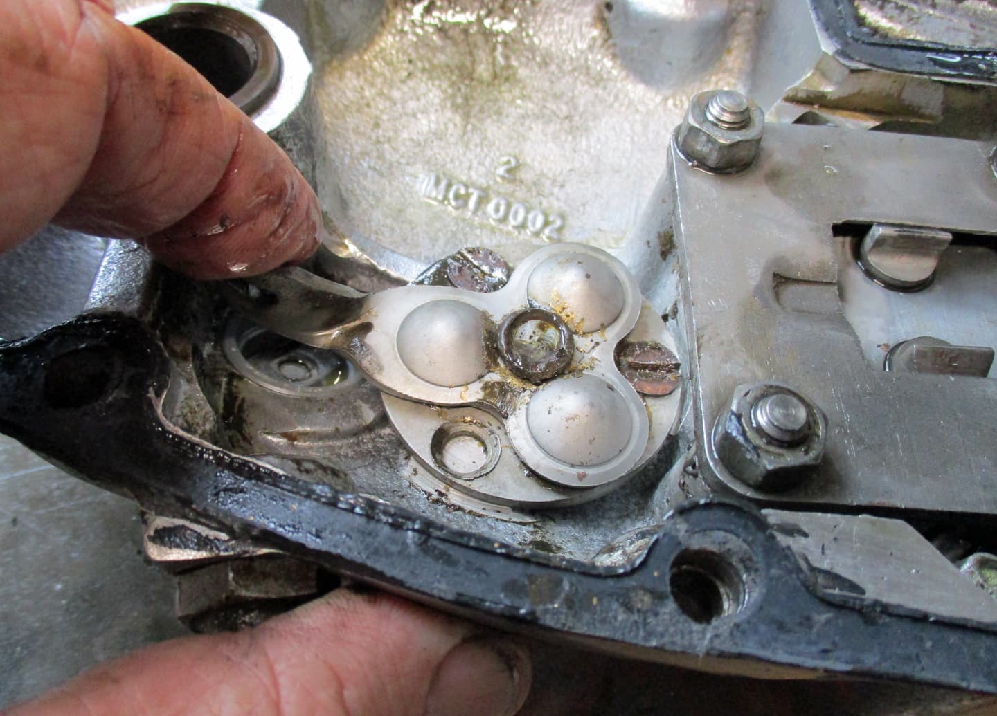
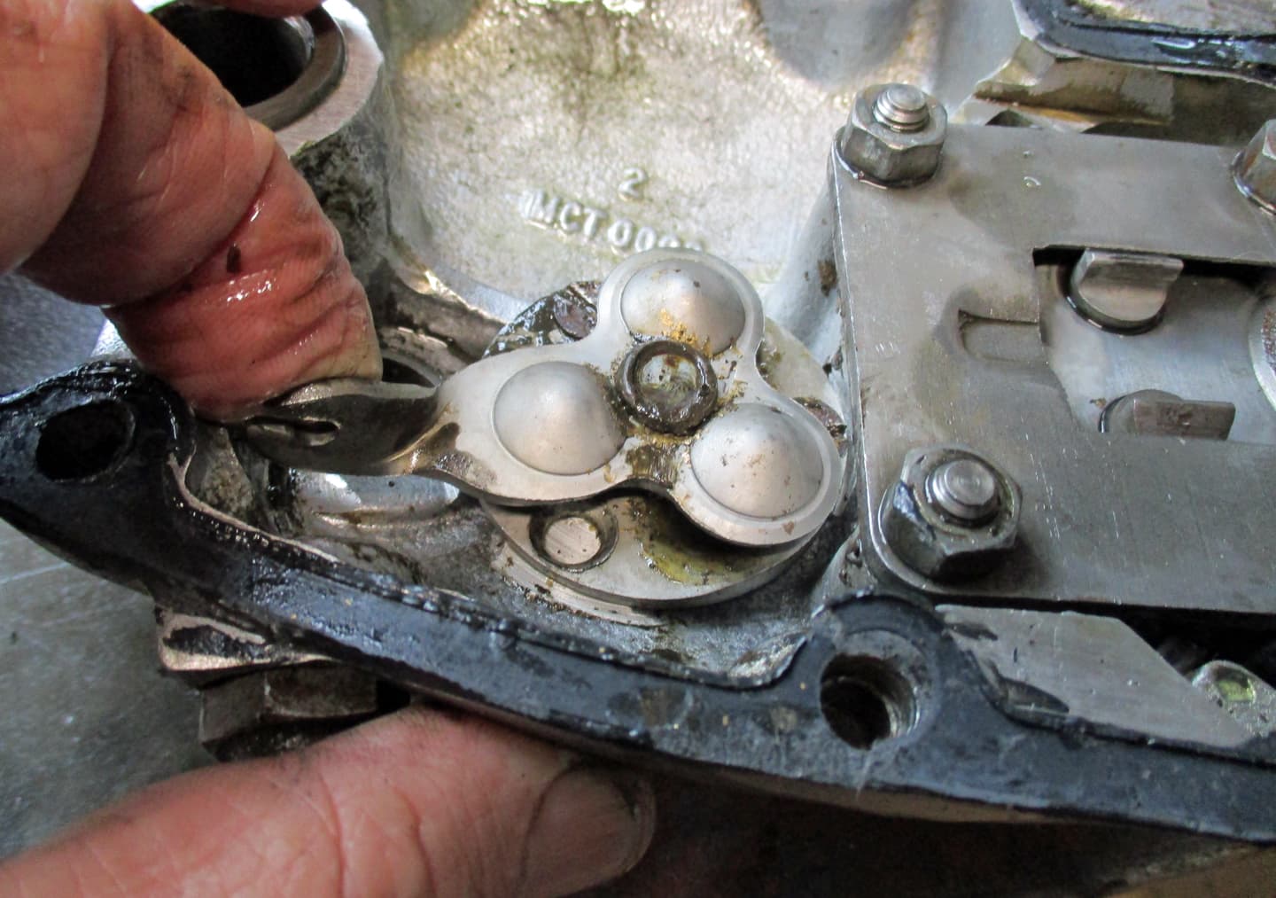
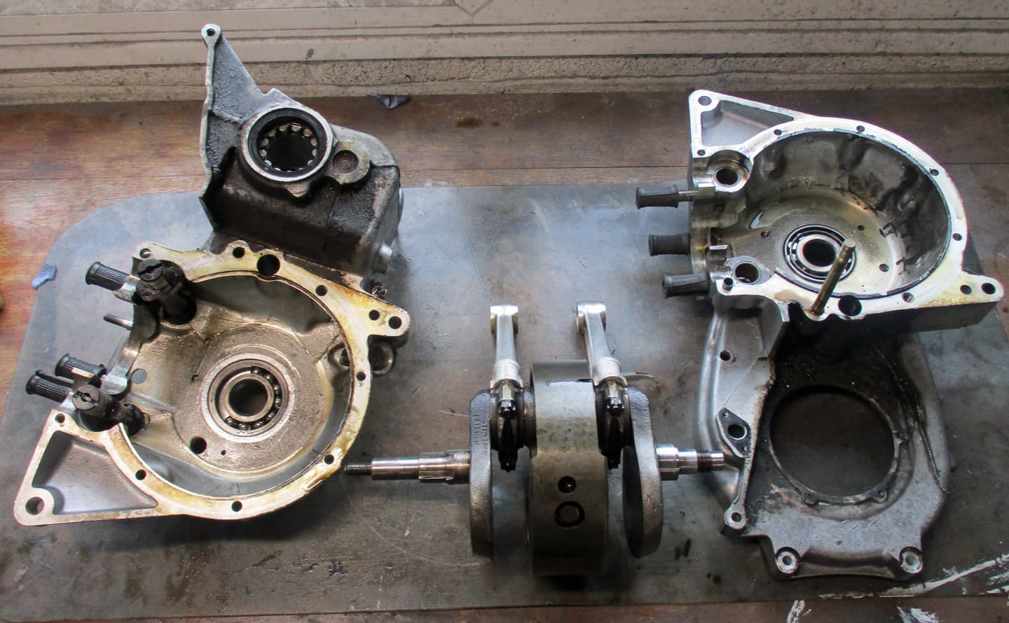
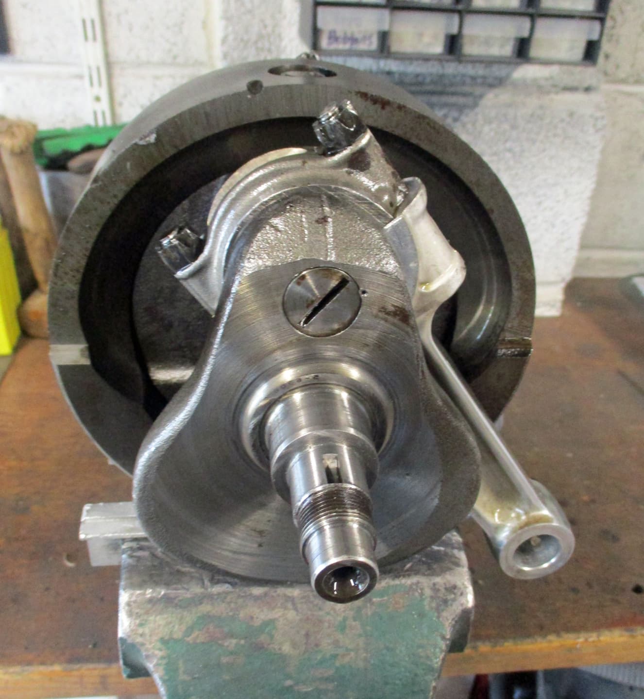
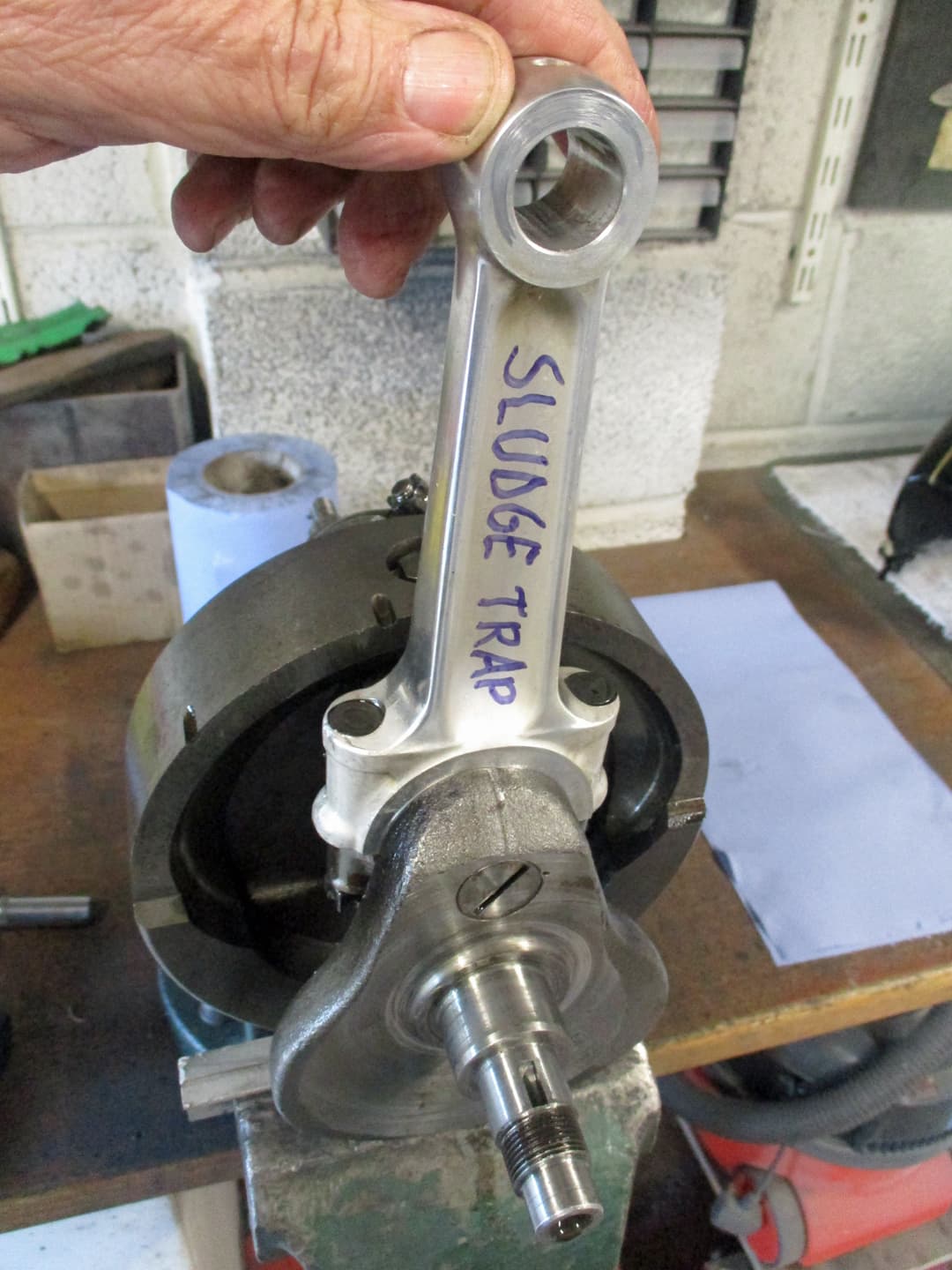
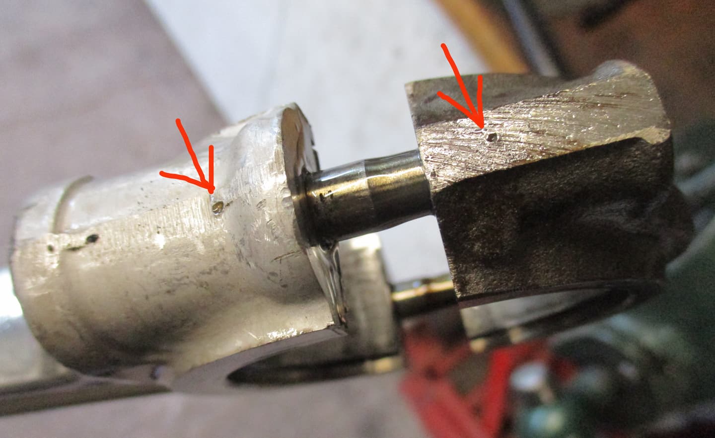
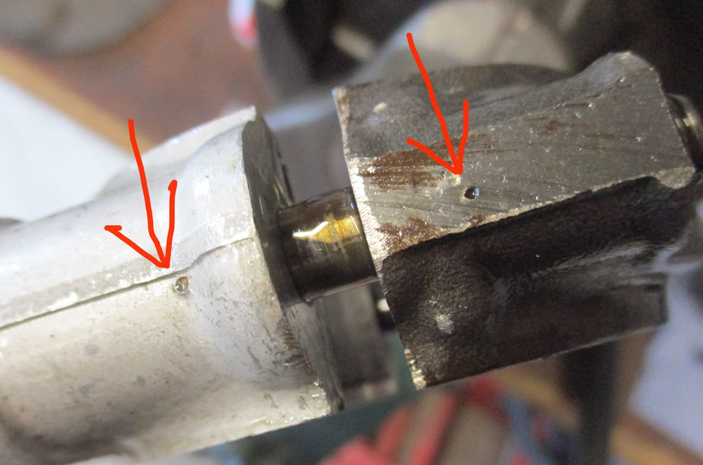
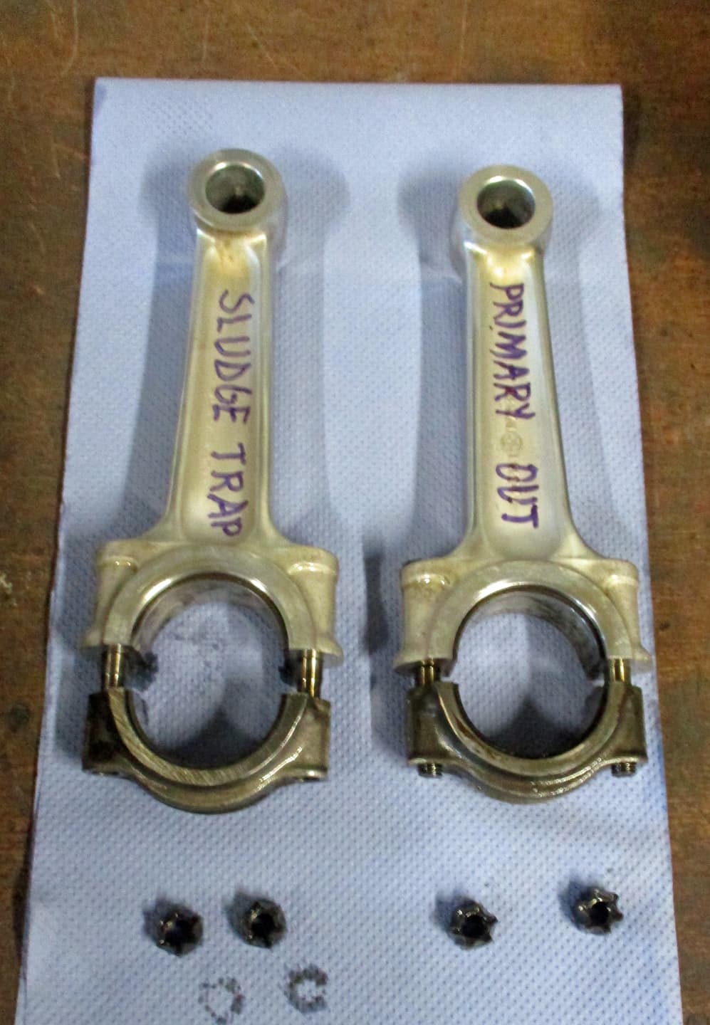
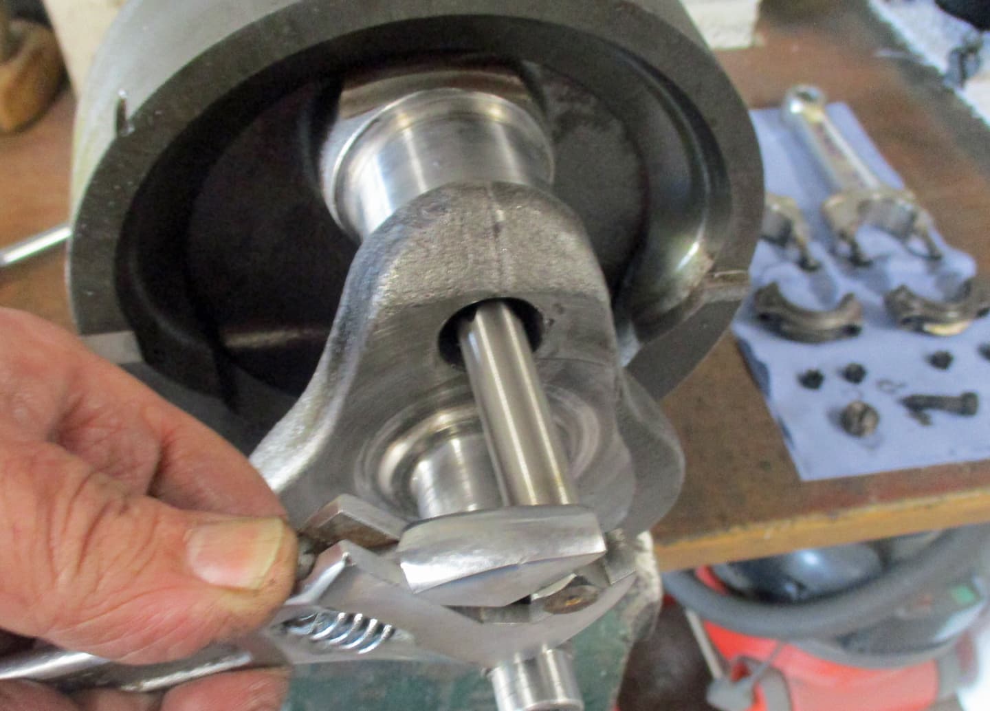
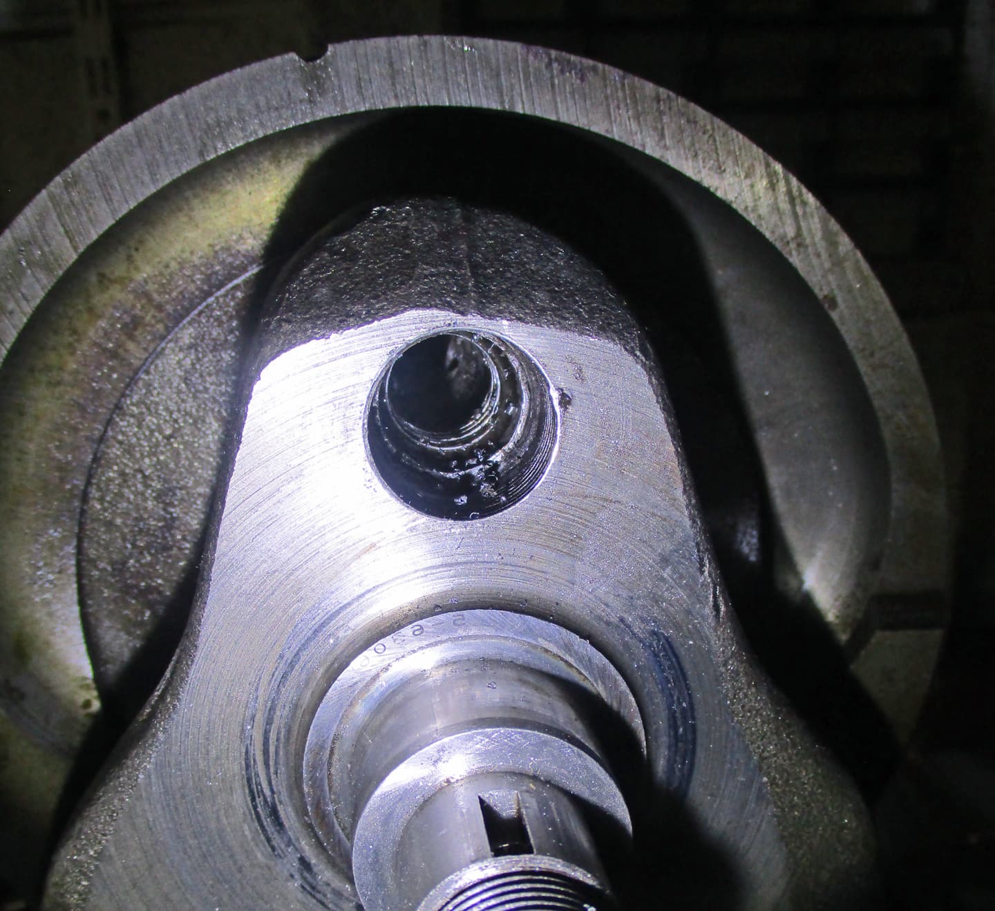
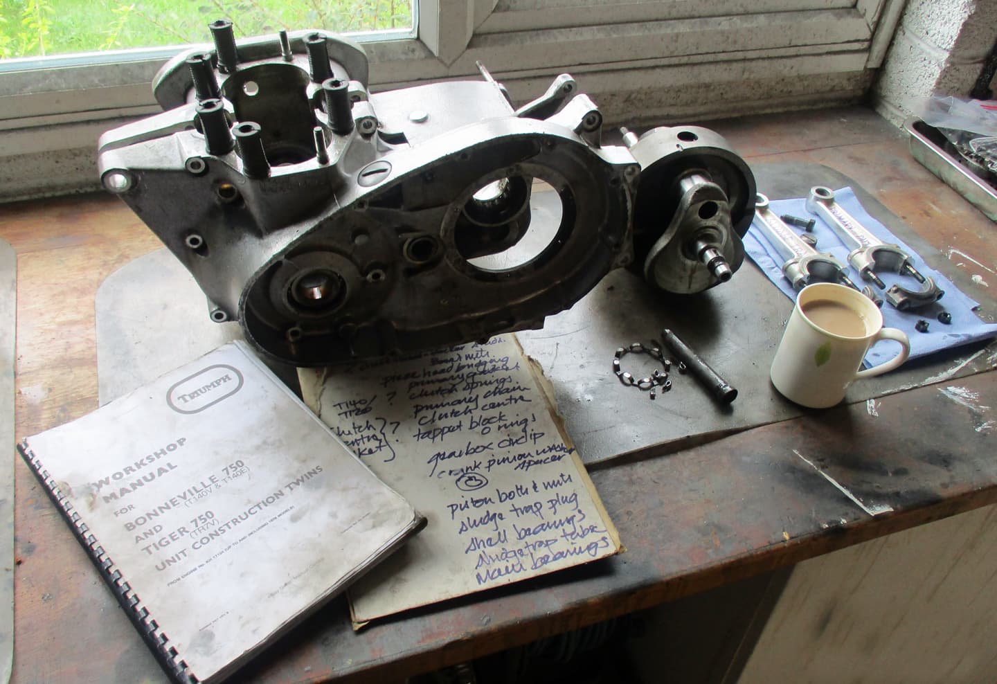
Without knowing the history of the machine, you never know what could be lurking inside. They really need to be stripped down to, at the very least, clean out the sludge trap. (I’ll explain what the sludge trap is later). A blocked sludge trap will ruin your whole day.
Never, ever, believe what a dealer tells you. I’ve bought several from dealers and they have all needed a rebuild.
I’m going to try to show and describe the way through an engine rebuild. I’m no expert at this, I have no expensive machinery or anything other than an ordinary owner’s garage. I have, however, done this a few times before.

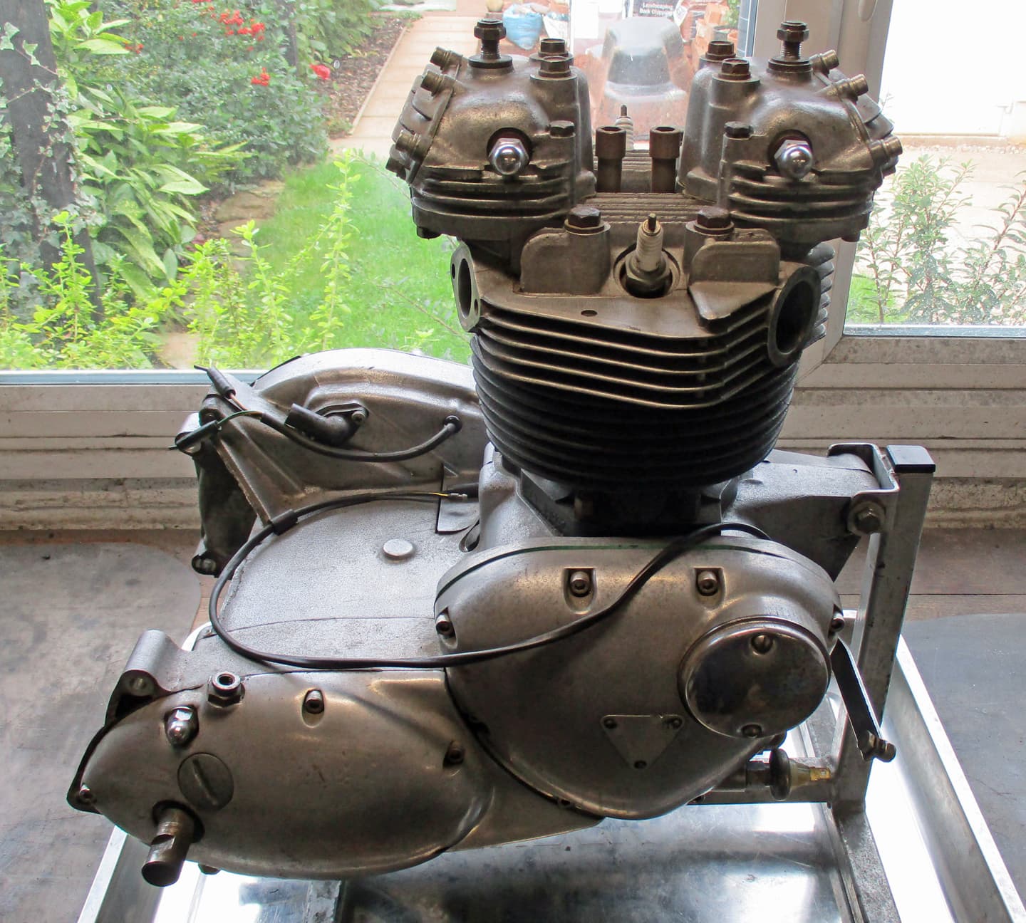
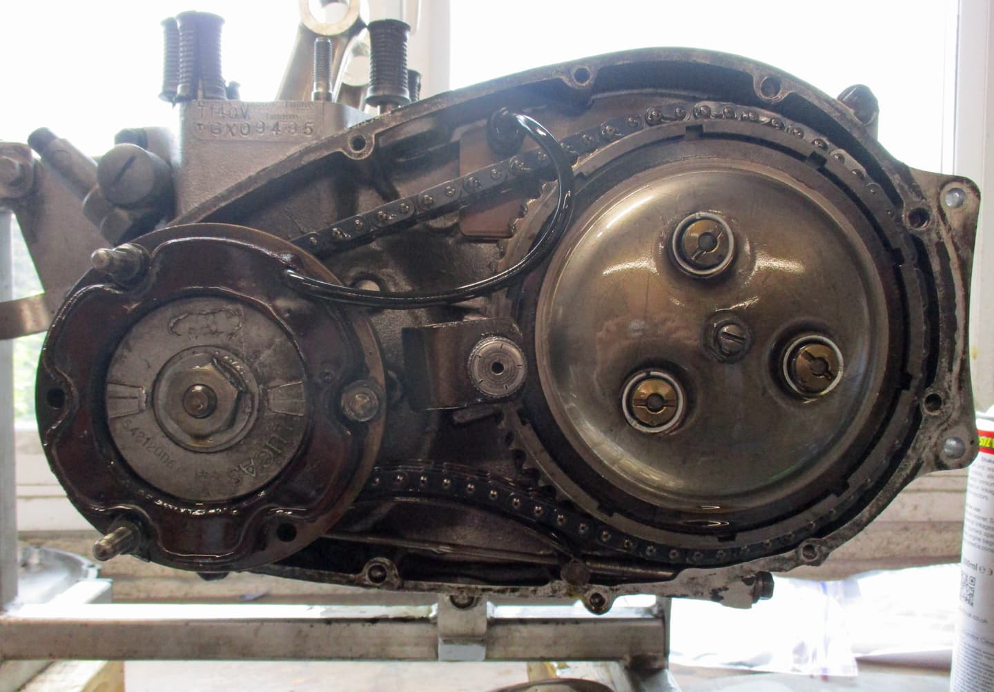
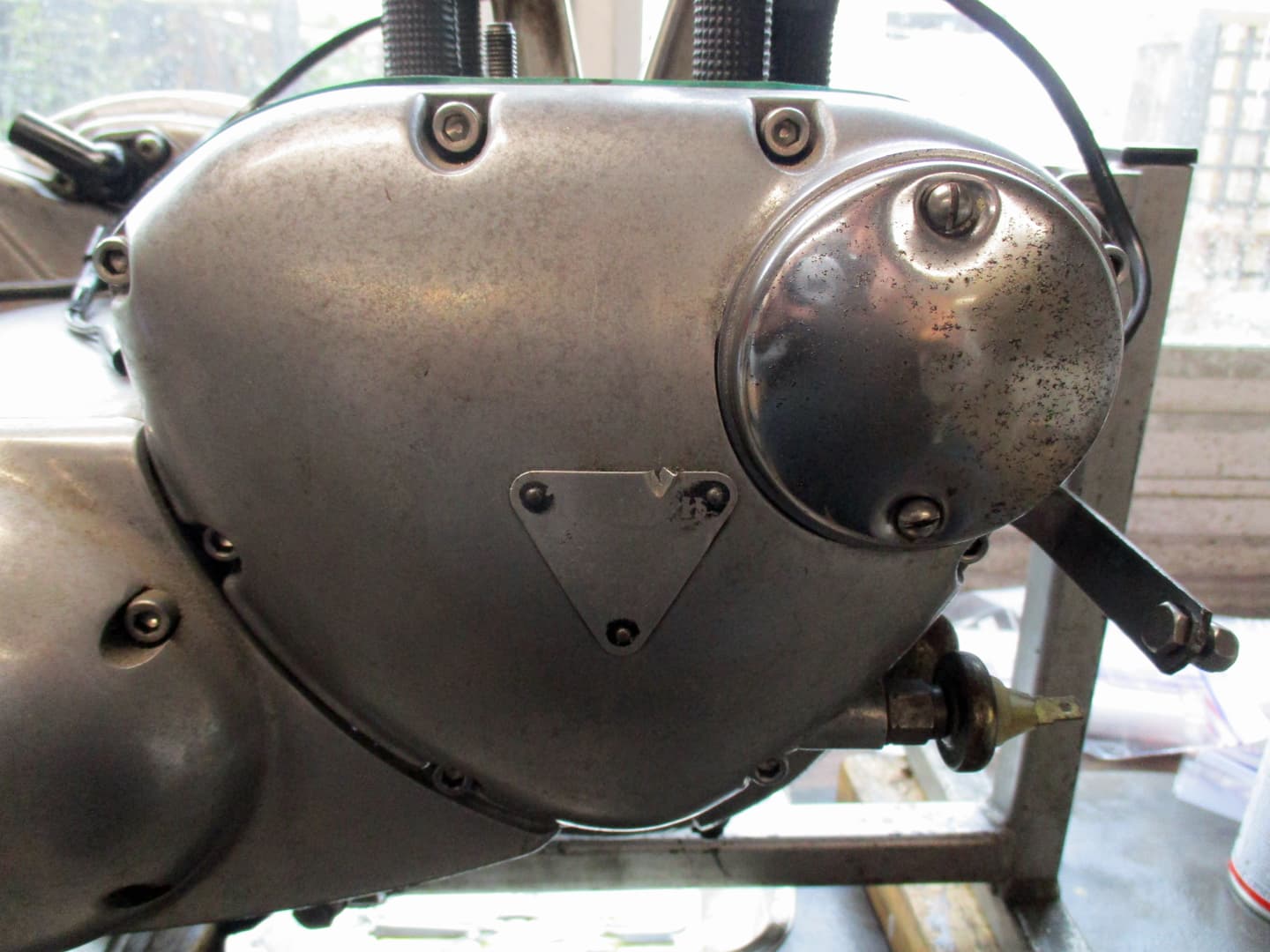
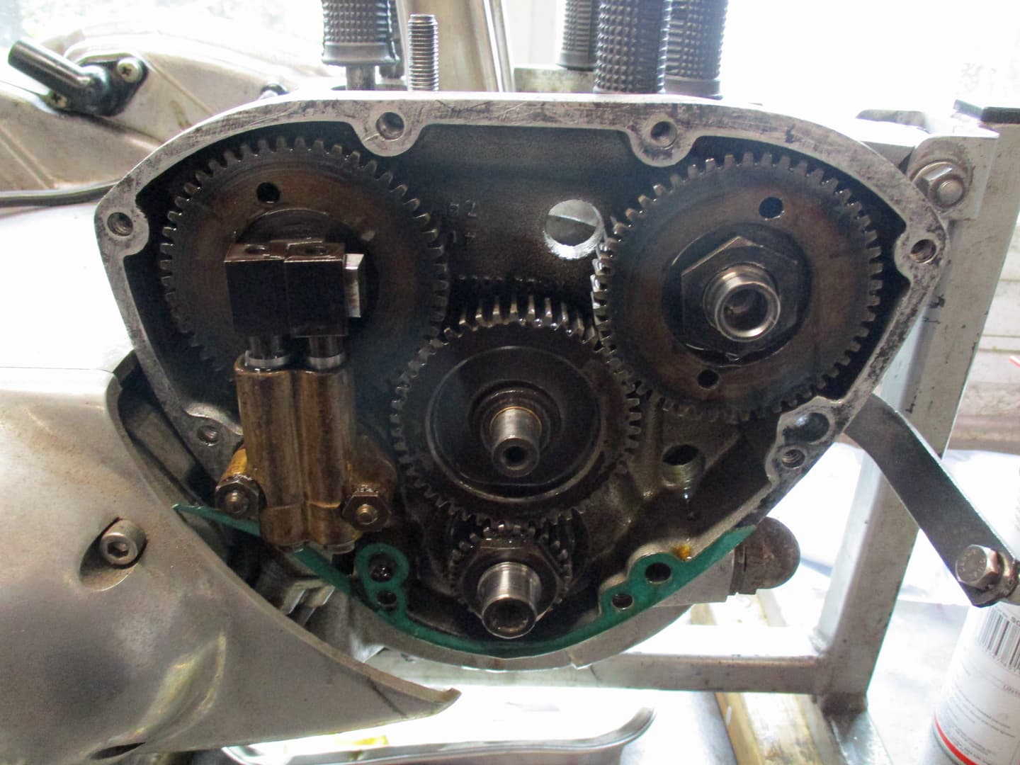
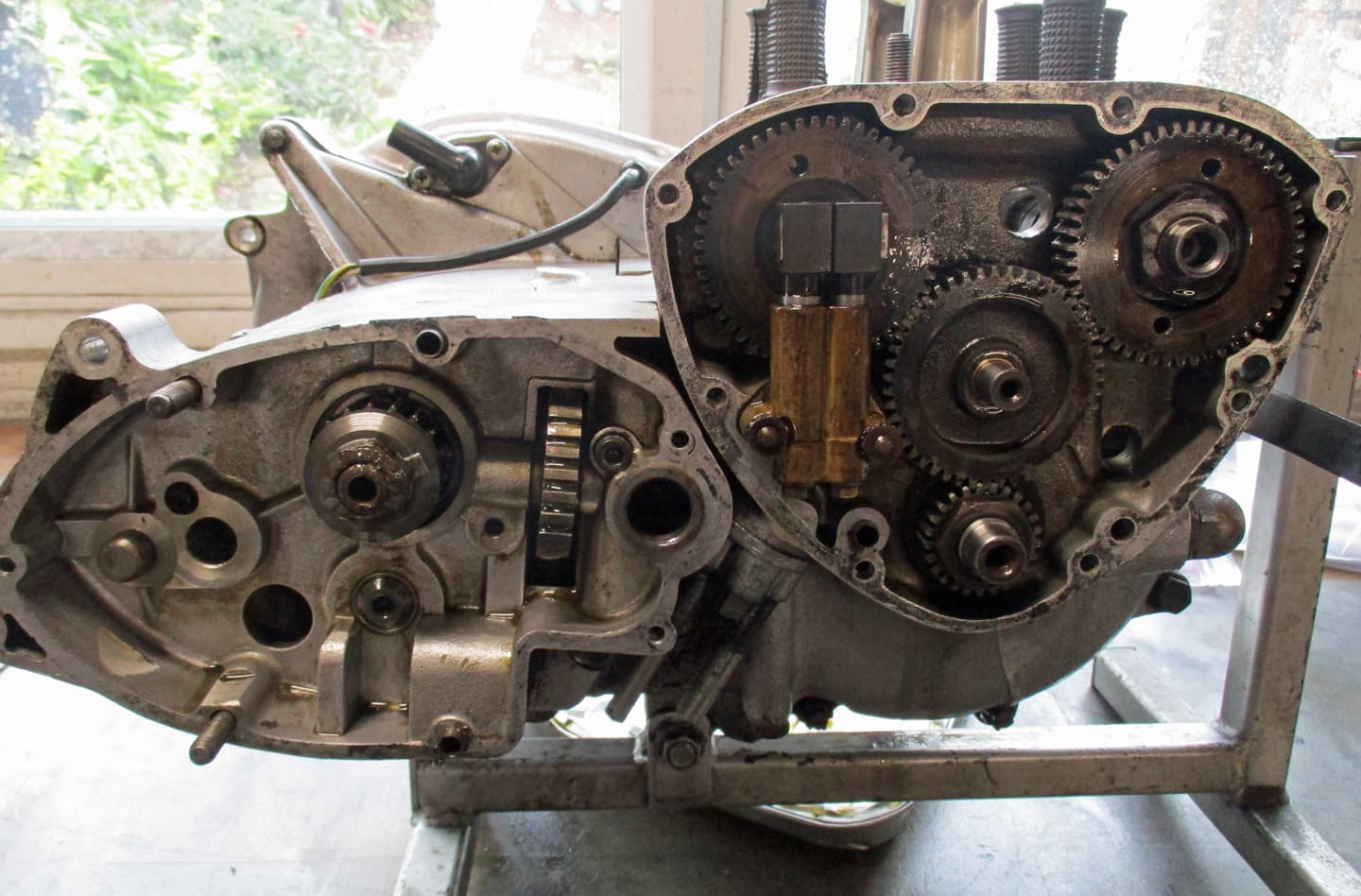
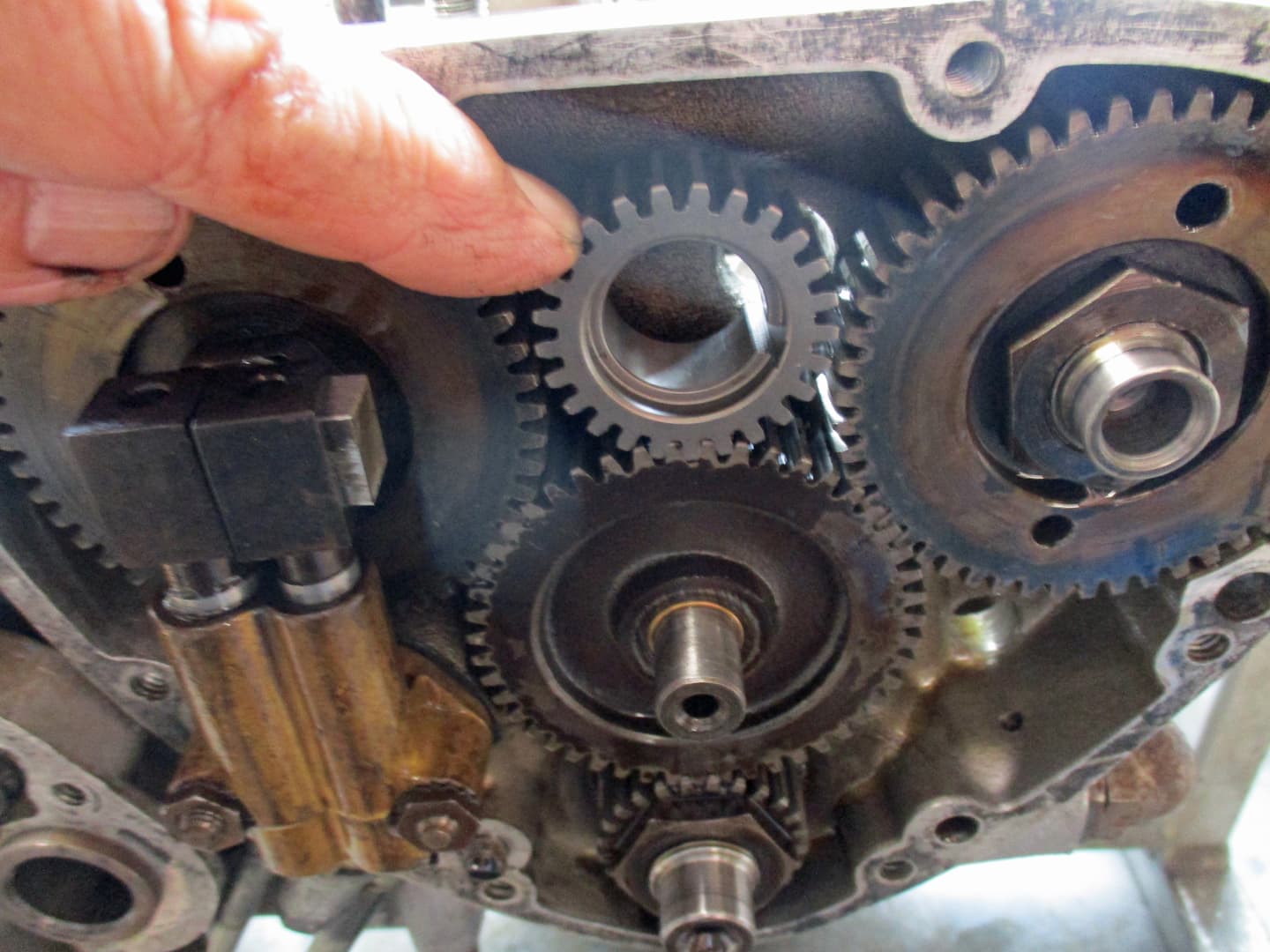
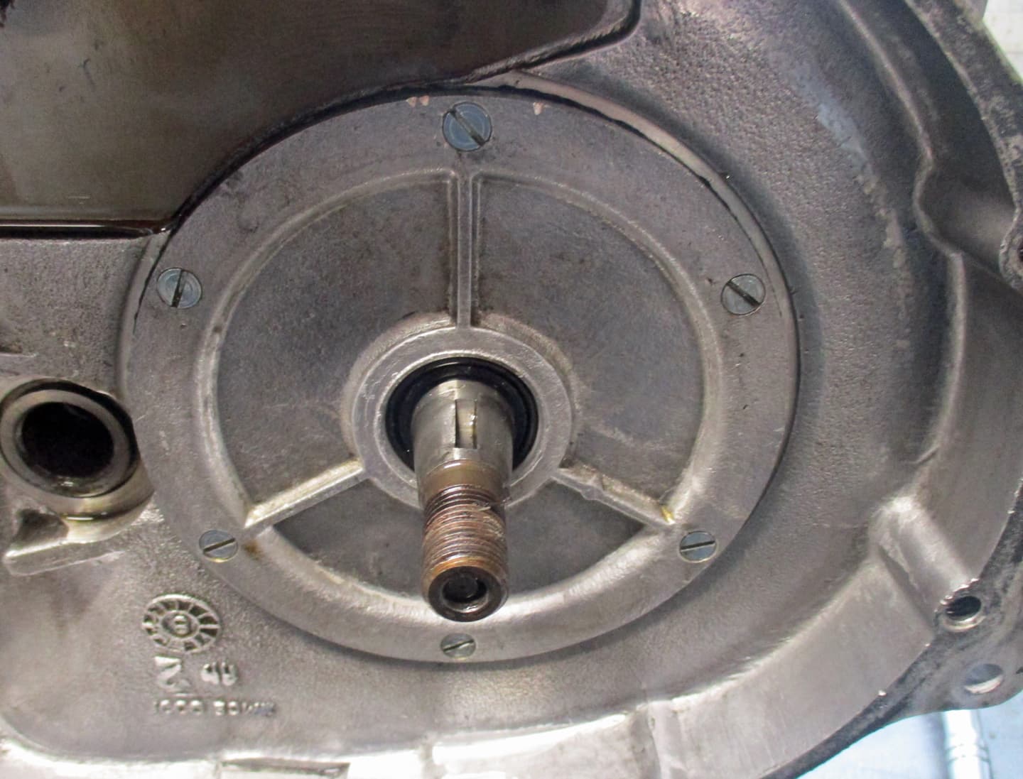
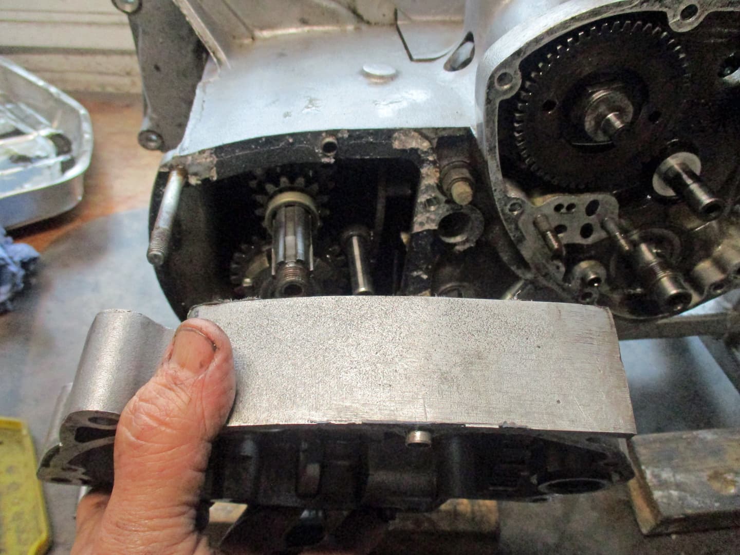
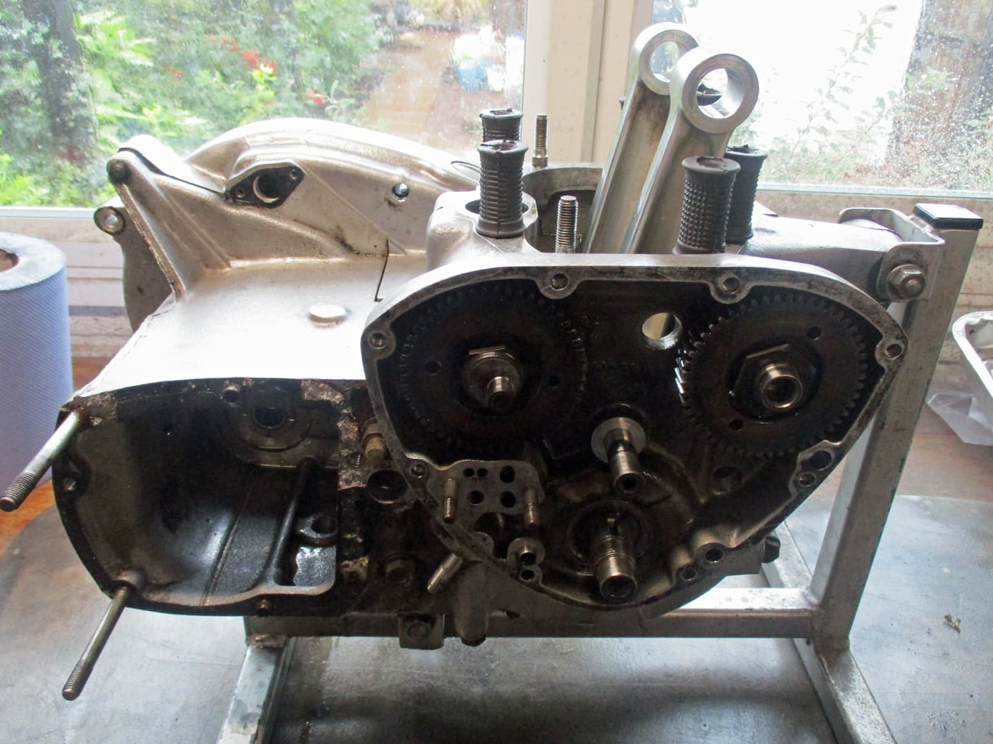
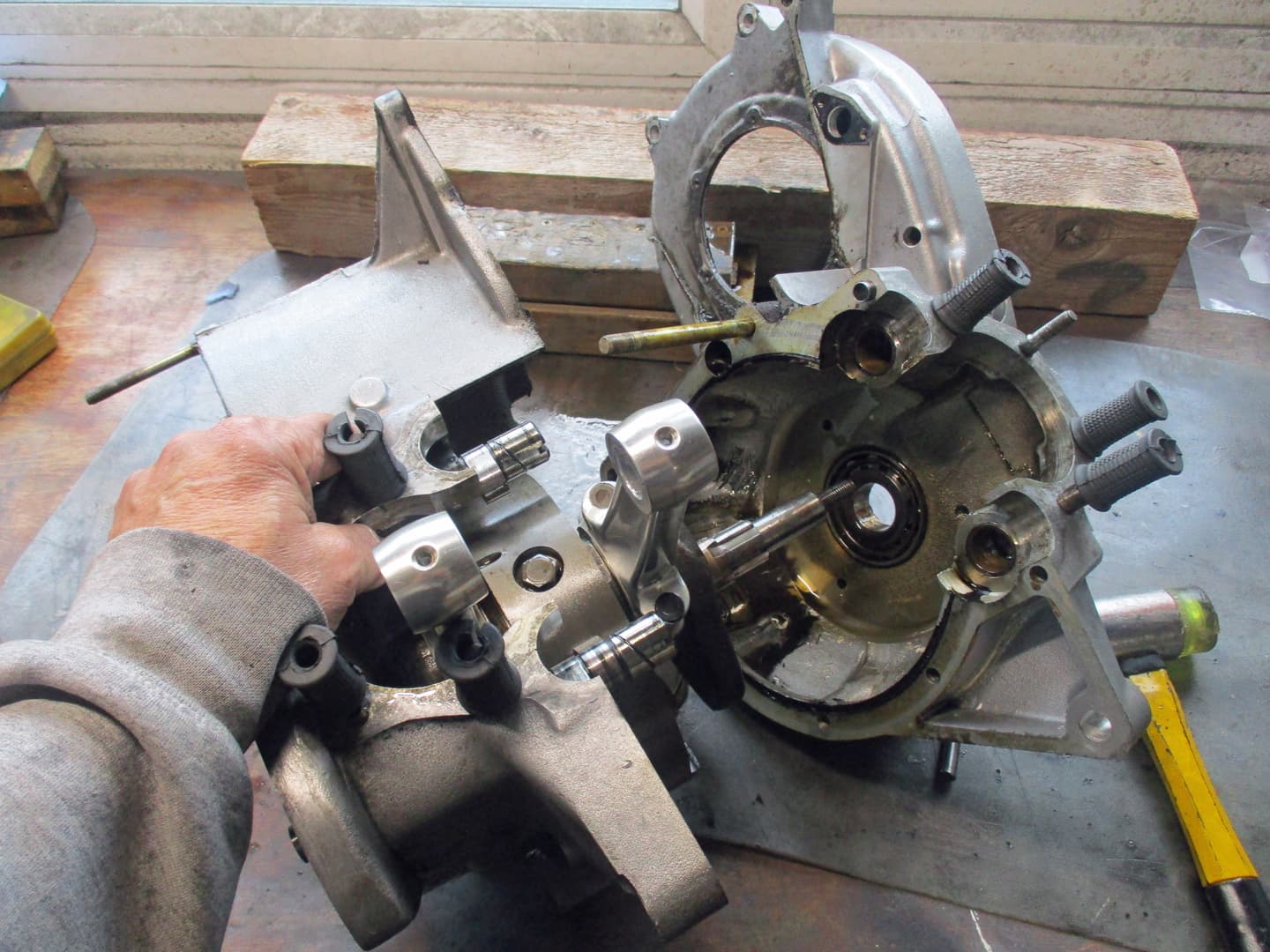
This is the right side of the engine. The facings are as you would sit on the bike. This side is the timing side. The original screws have been replaced by allen bolts so work has been done at some point.
The oval shaped section is the gearbox, the triangular section contains the timing gears with the contact breaker points in the circular cover. (This engine has already been converted to electronic ignition so the points are gone replaced with a Bower Branson system - a pretty simple system to install but we’ll cover that later).

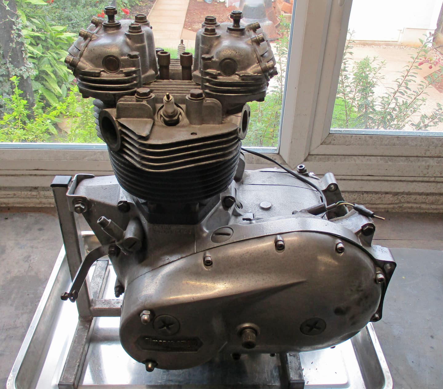
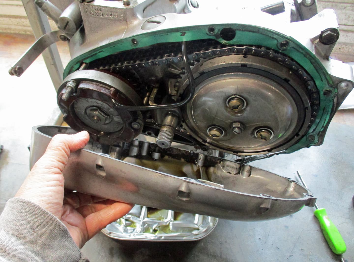
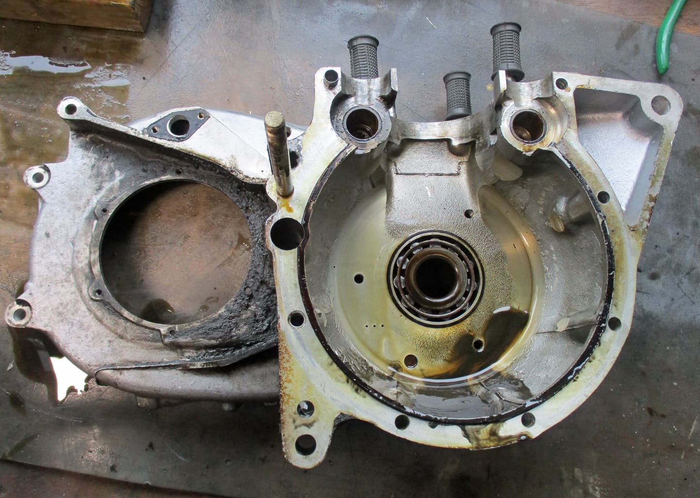
The left side of the engine. This side is the primary side that contains the stator (charging system) and the clutch. This side (after the earlier 70s machines) has the gear change lever. (regulatory right side brake lever for exported models so a change was made). Again, original screws have been replaced with allen bolts.

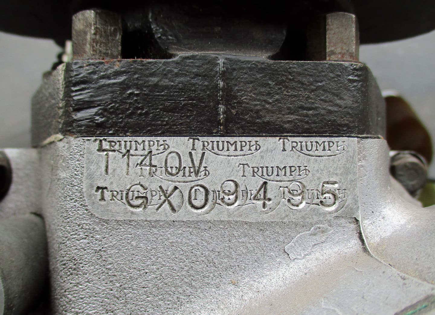
Just below the barrels the left side casing is stamped with the engine number. When new, both the frame and engine had the same number. Matching numbers are preferred by buyers.
The Triumph Logo was stamped across to deter fakers replicating numbers.
T140V is the type - a Triumph 750cc with 5 gears.
The next two letters G and X are the manufactured date - as shown on here:

G being June and X being 1978.
The remaining numbers are the specific machine off the line.

Sometimes a few more details can be obtained from the Triumph Owners Club (it’ll cost you membership to apply) or the Vintage Owners Club who also have original documents and help with registration numbers etc if you are importing or bringing an unregistered machine back to life

The Vintage Motor Cycle Club - Library and DVLA Forms

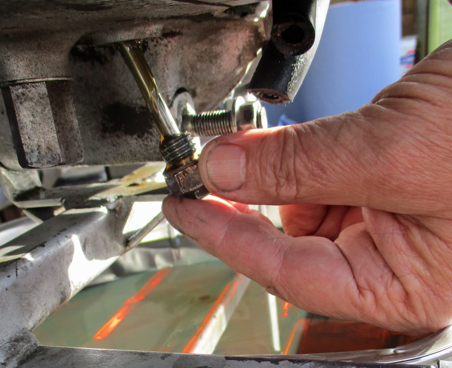
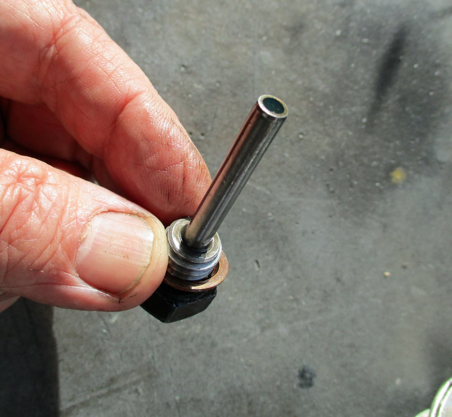
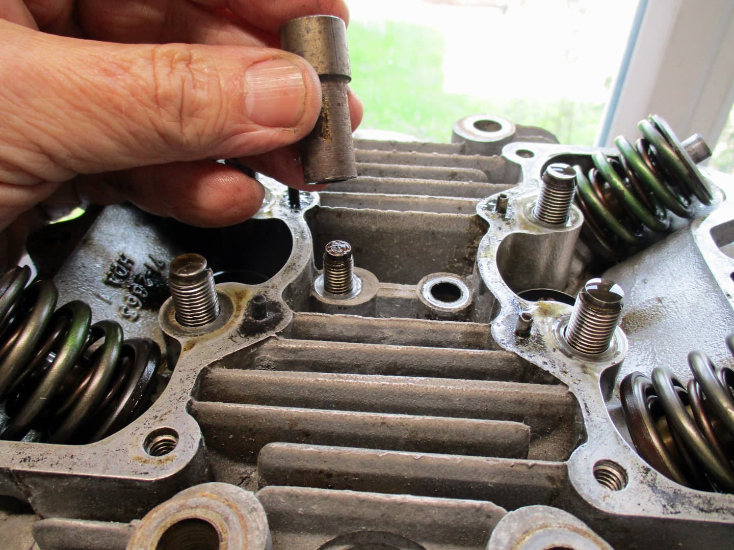
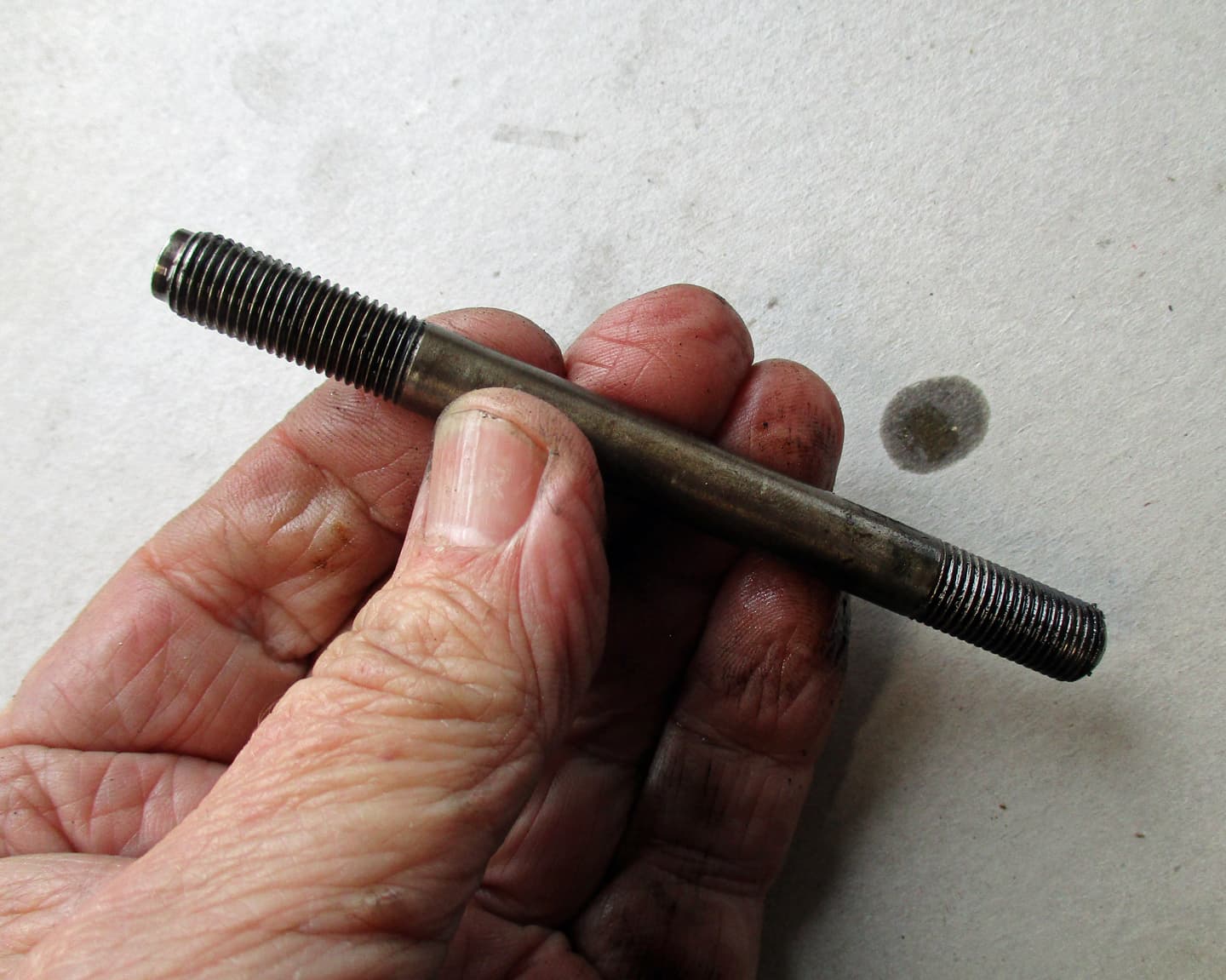
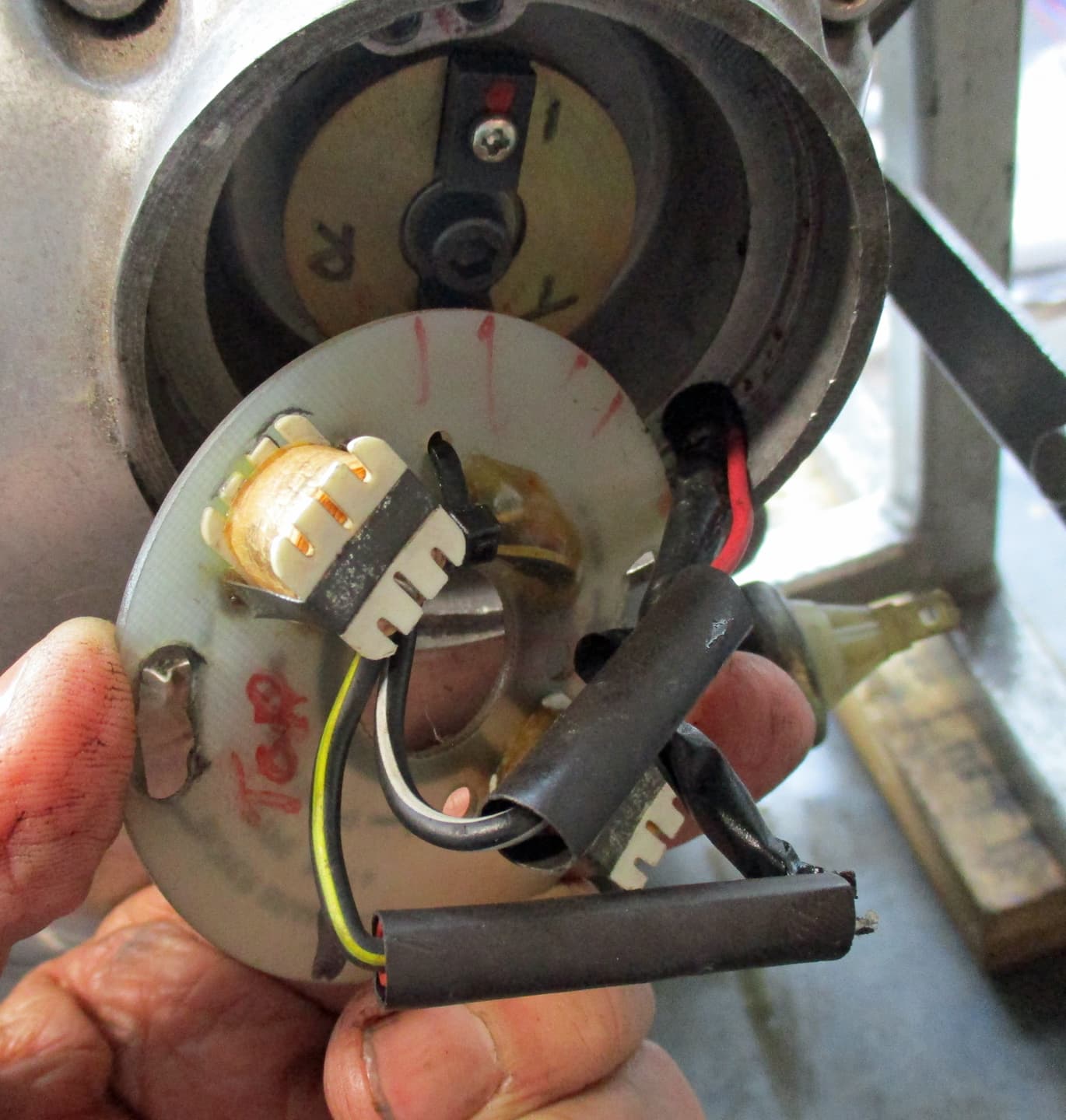
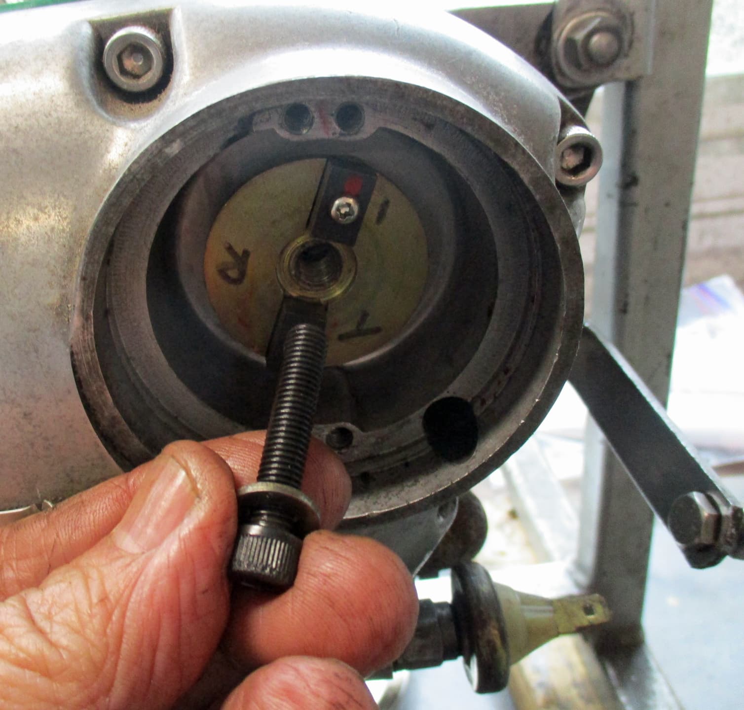
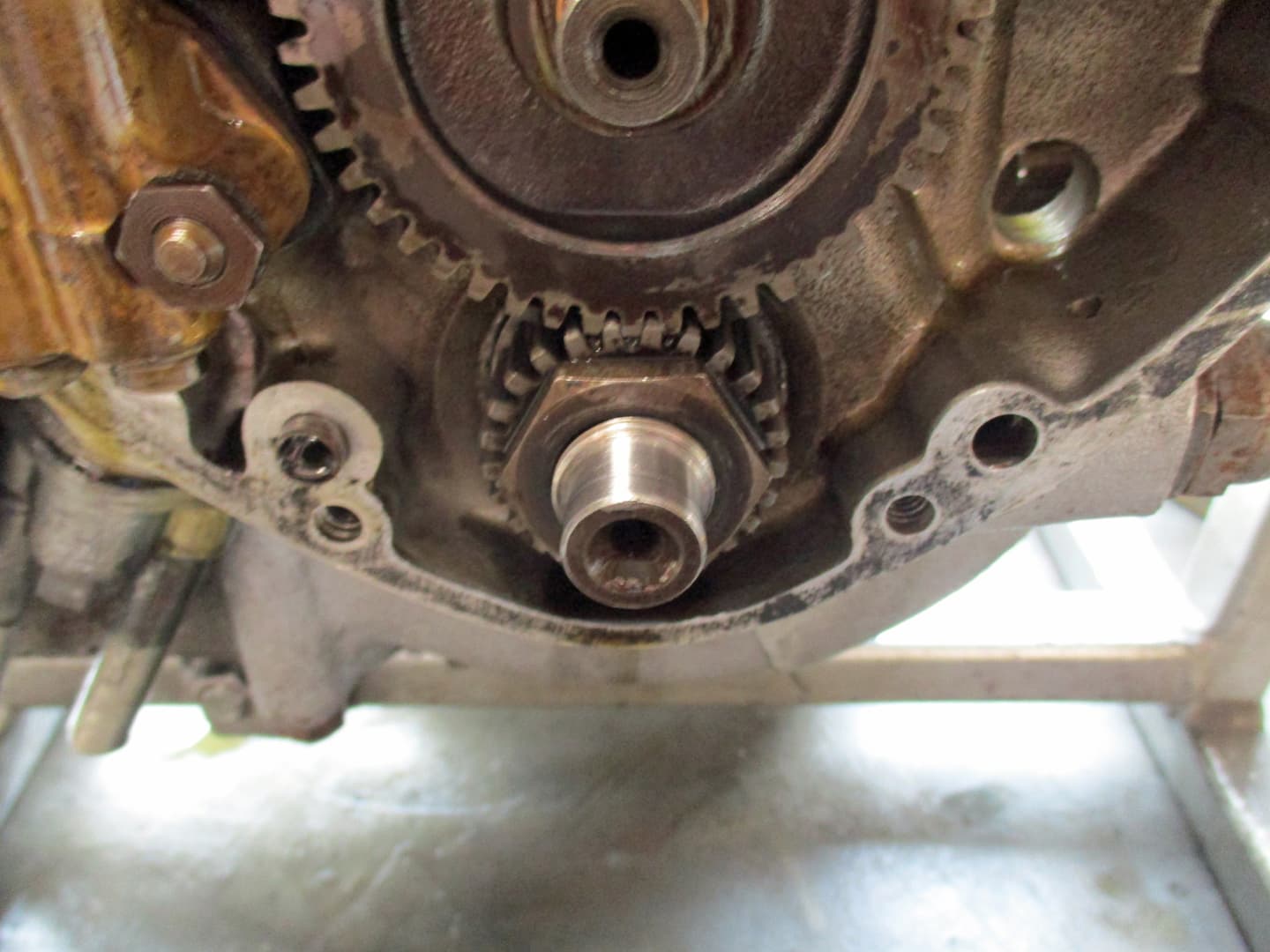
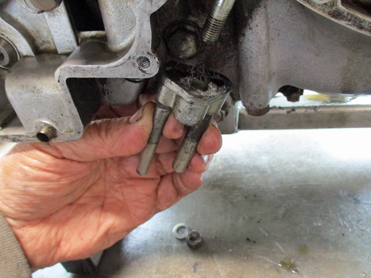
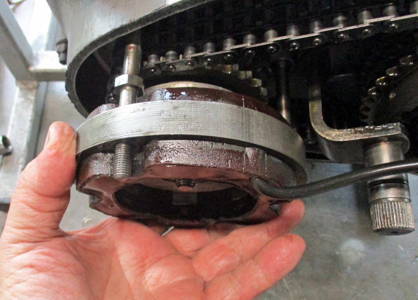
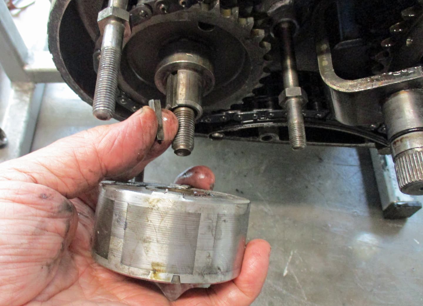
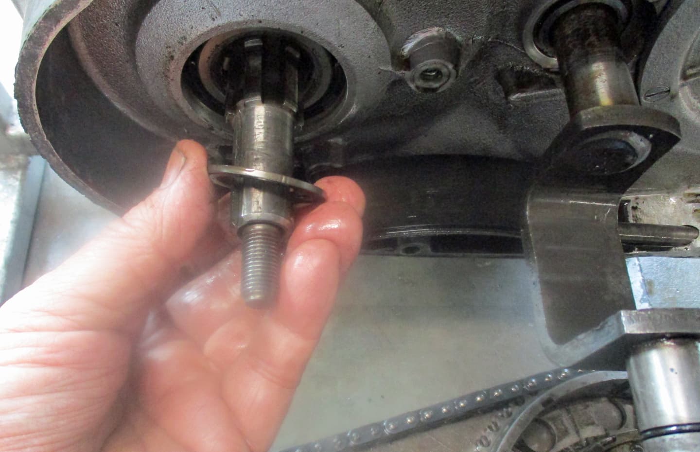
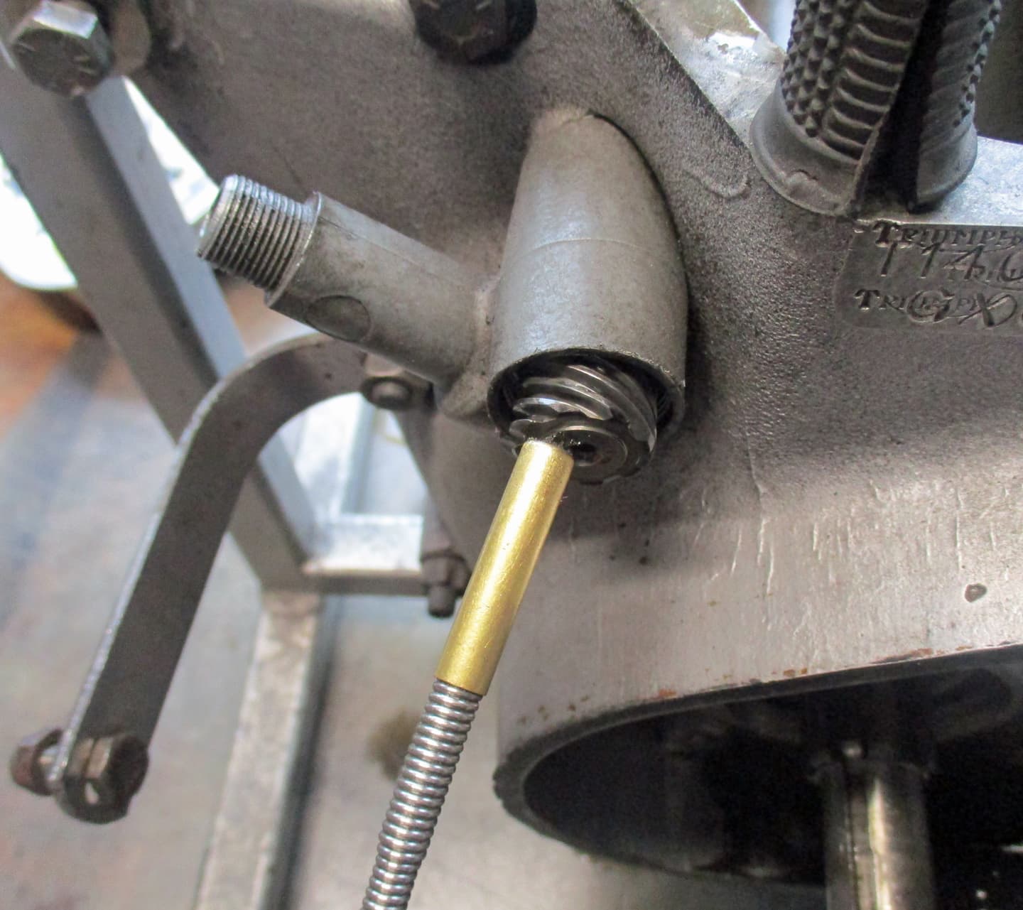
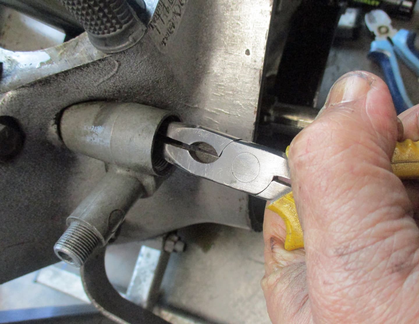
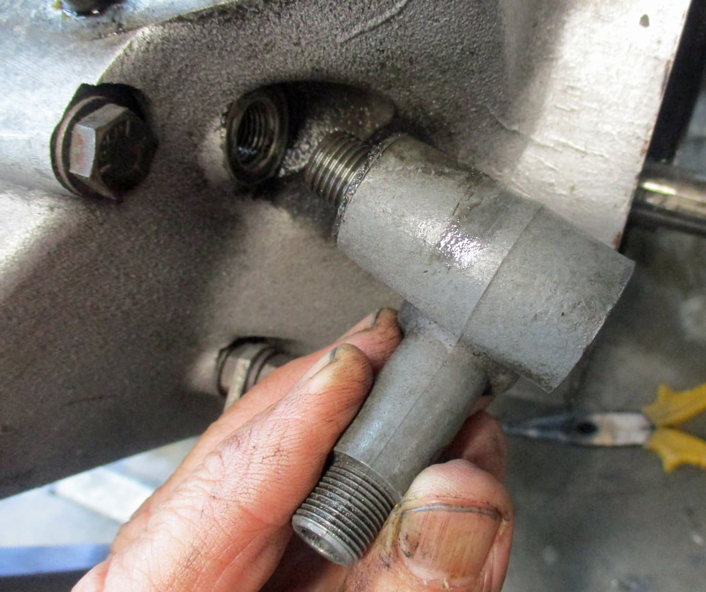
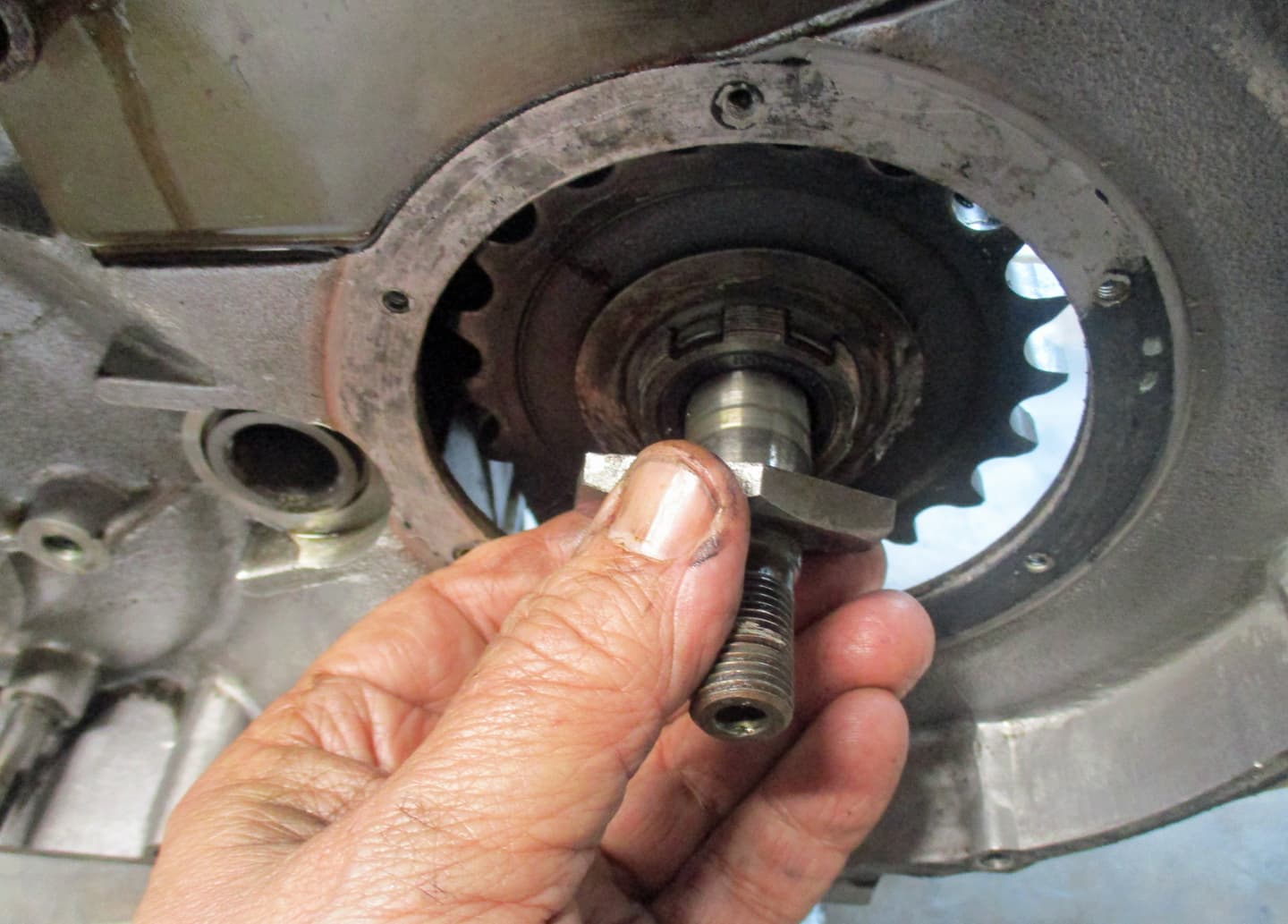
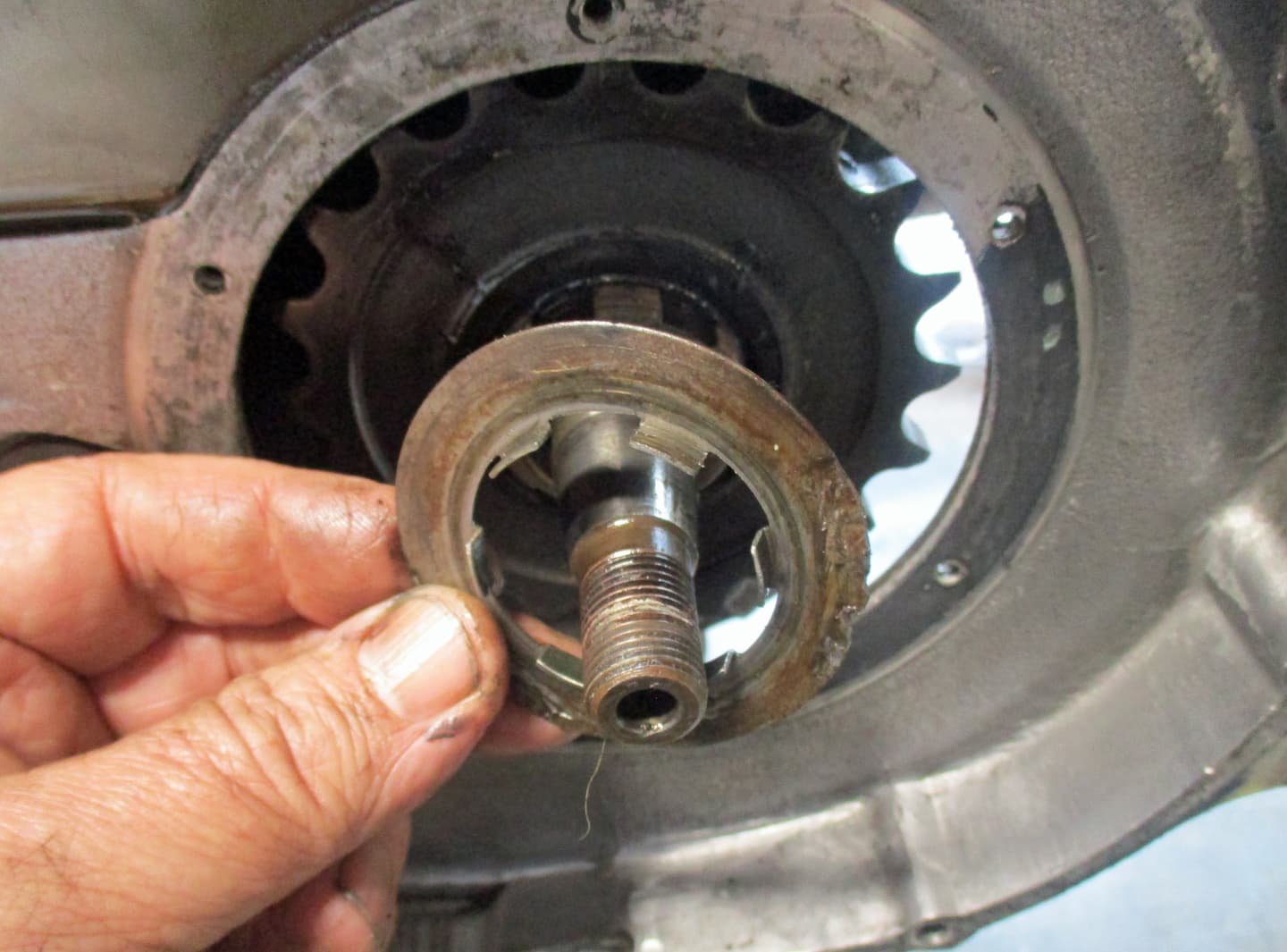
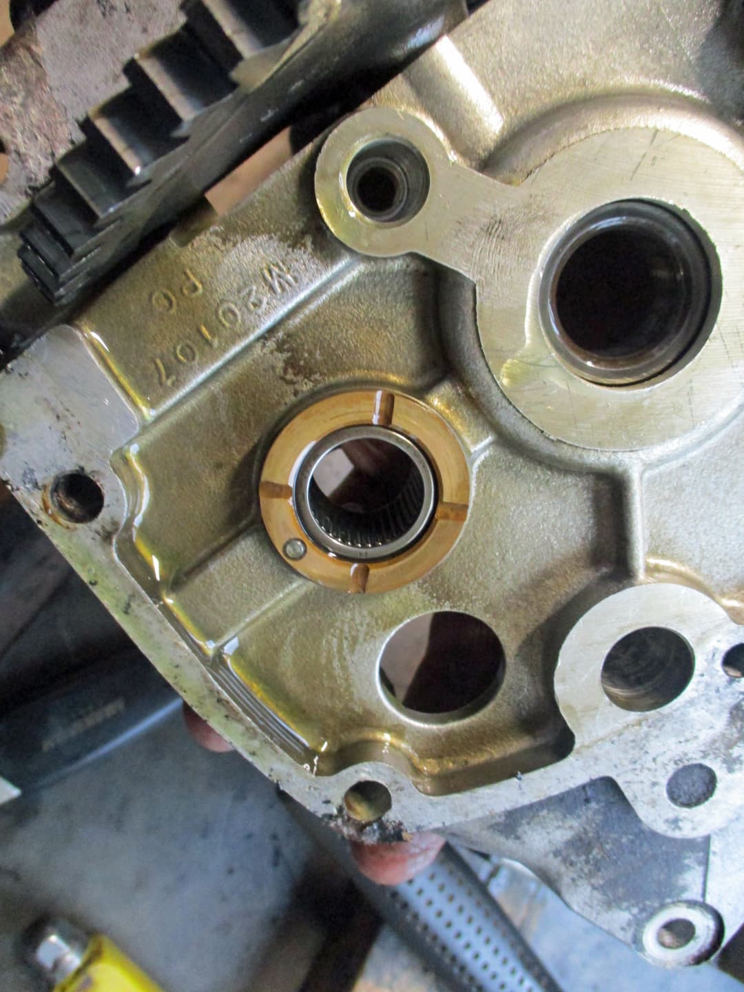
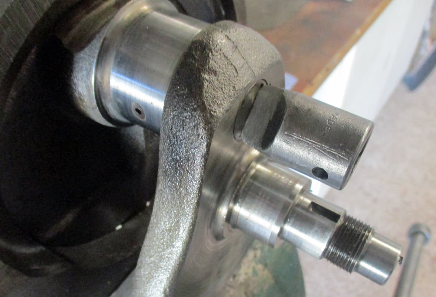
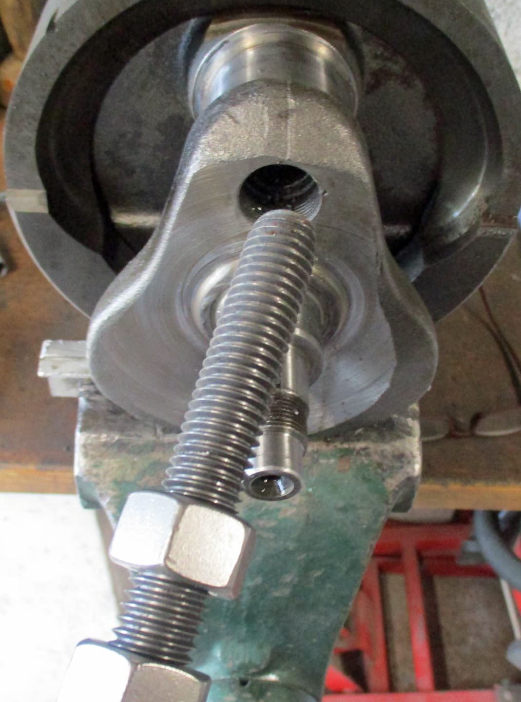
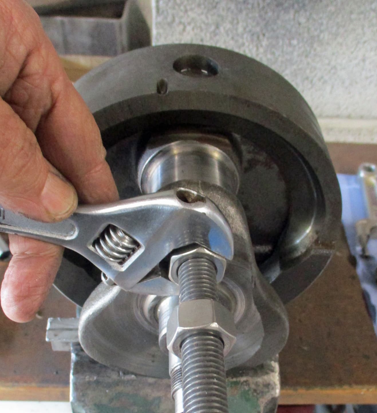
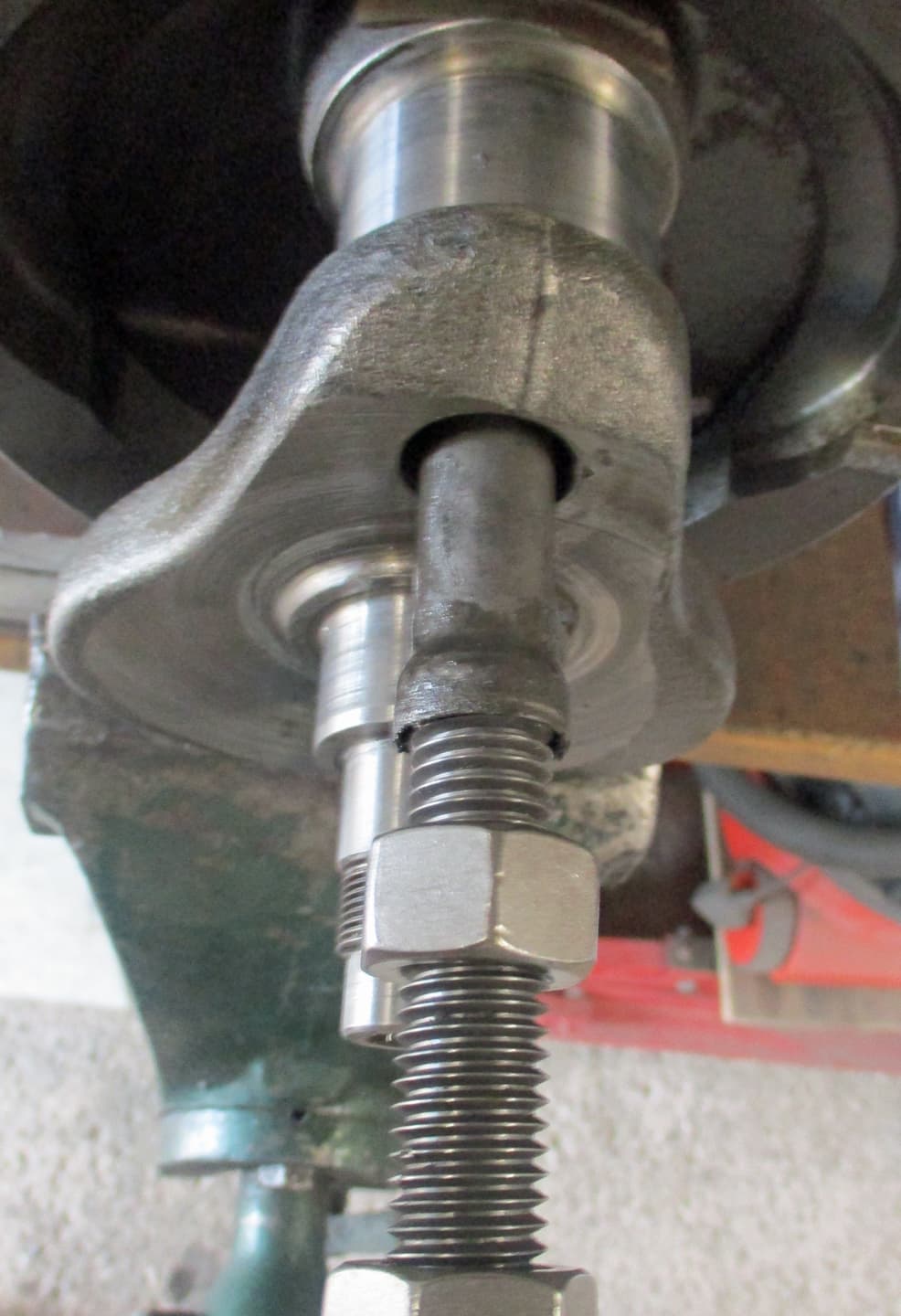
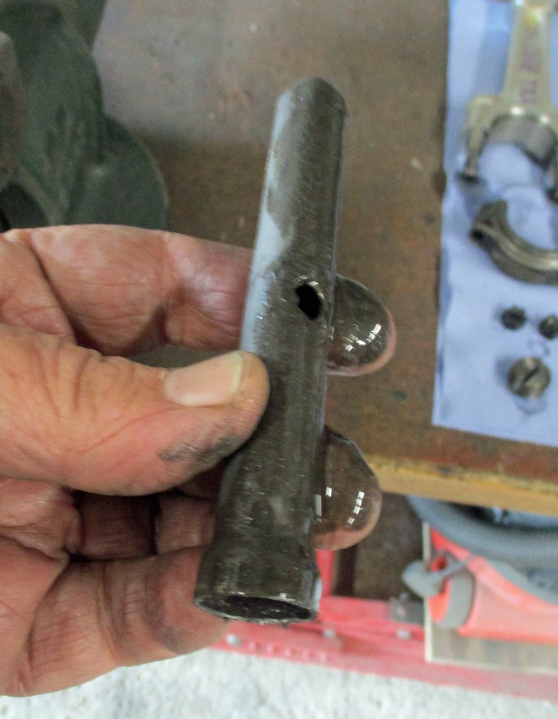
This is the rev counter drive. Sometimes kept, sometimes removed, sometimes left hand thread, sometimes right handed thread. We’ll find out what this one is later.

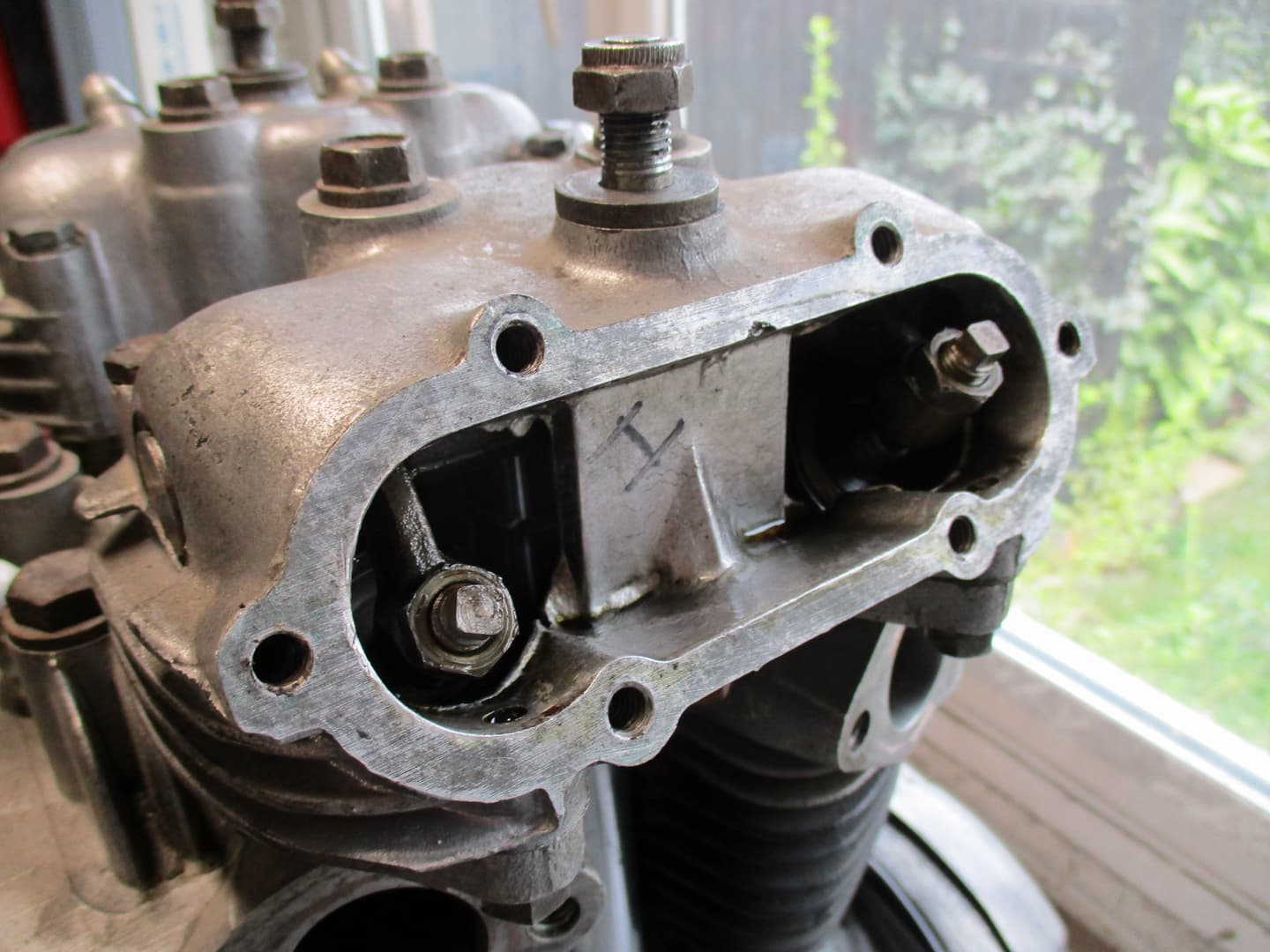
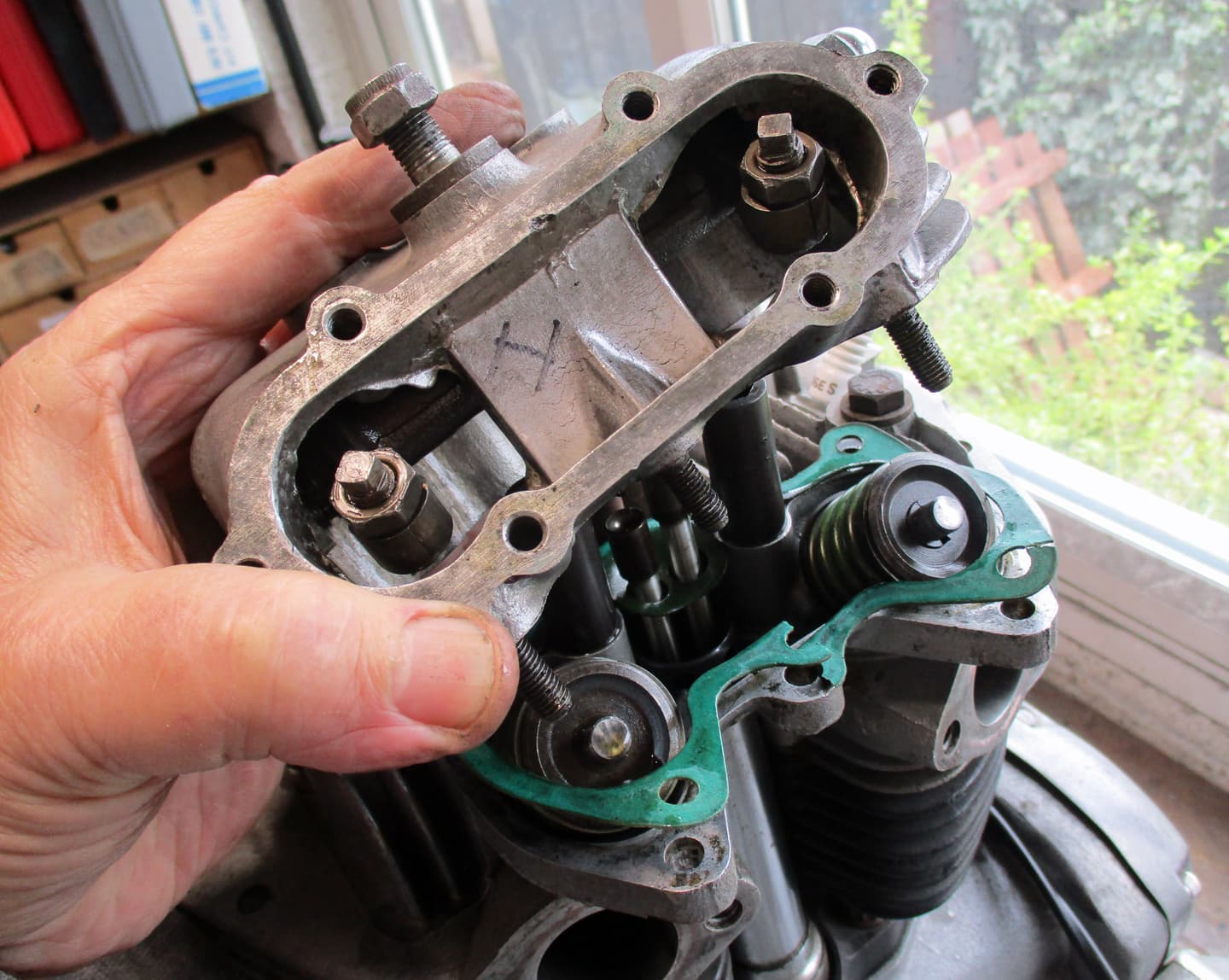
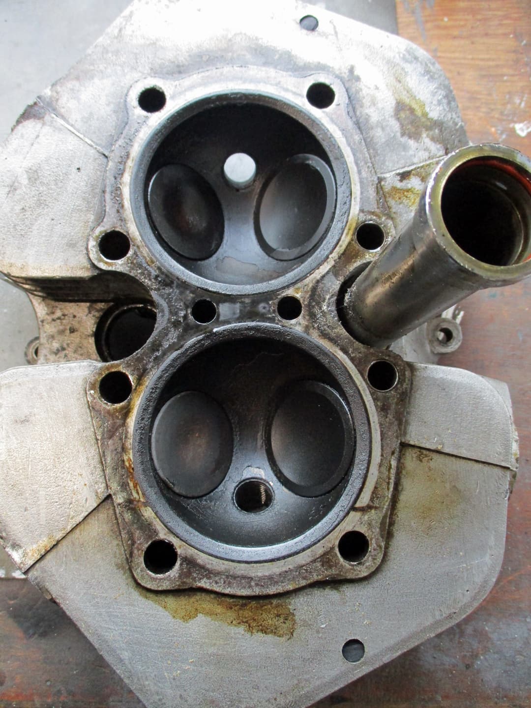
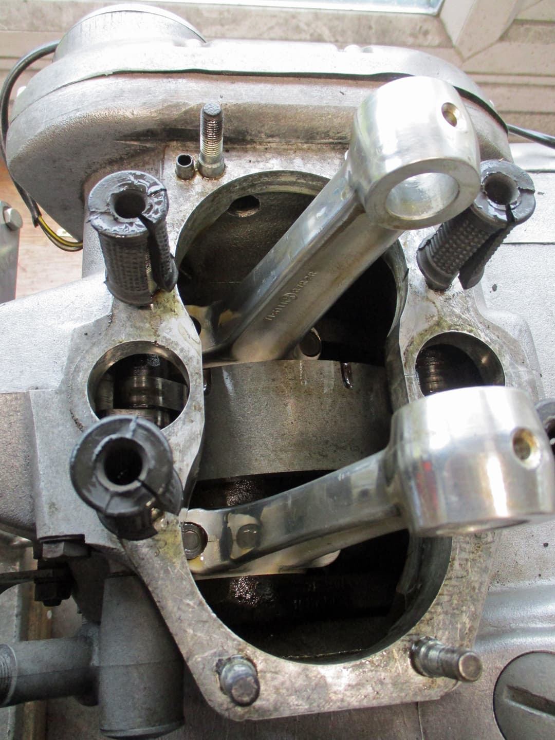
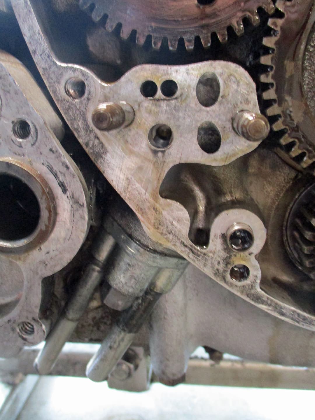
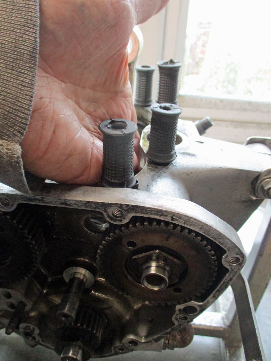
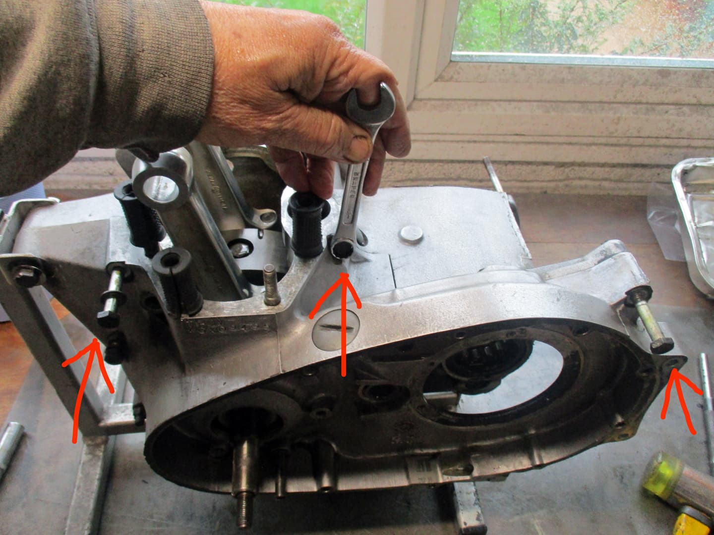
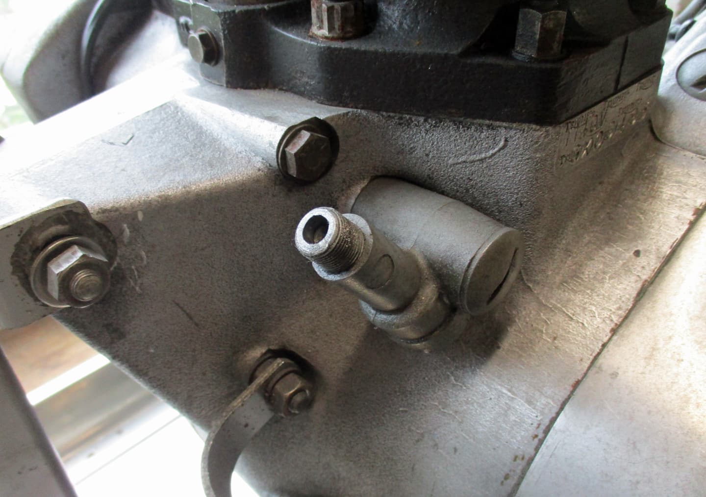
This is view looking up towards the rocker boxes from the inlet side. Note the three nuts. Previous mechanics may have missed these when trying to remove the rocker boxes with a large hammer thinking it is stuck. I’ve seen a few of these welded where they’ve been snapped - check here when buying.

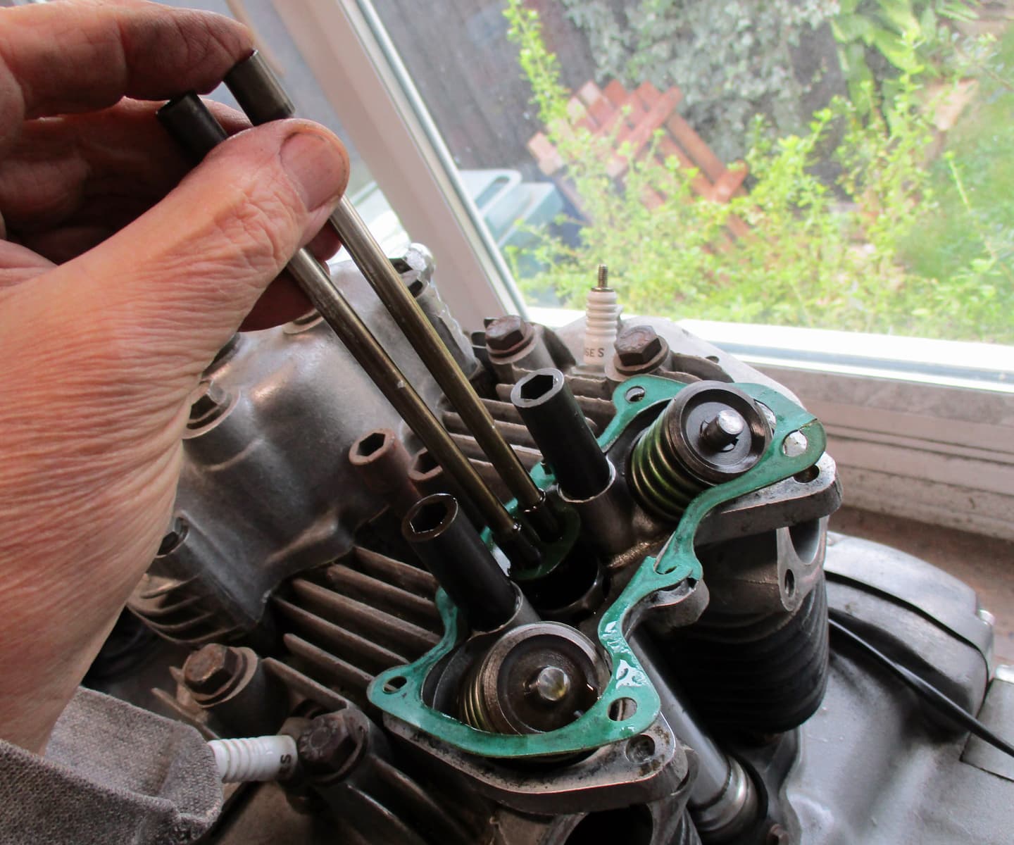
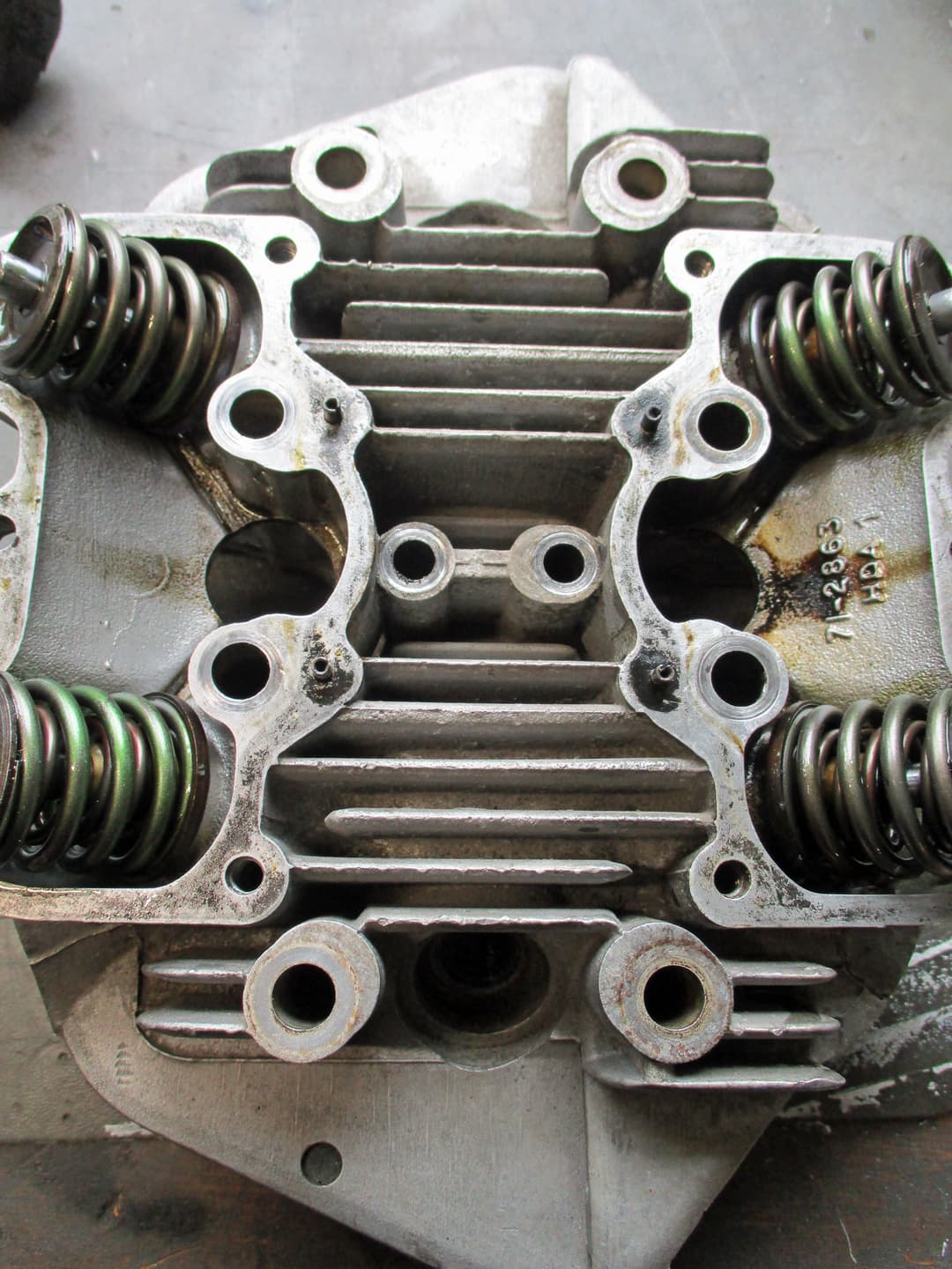
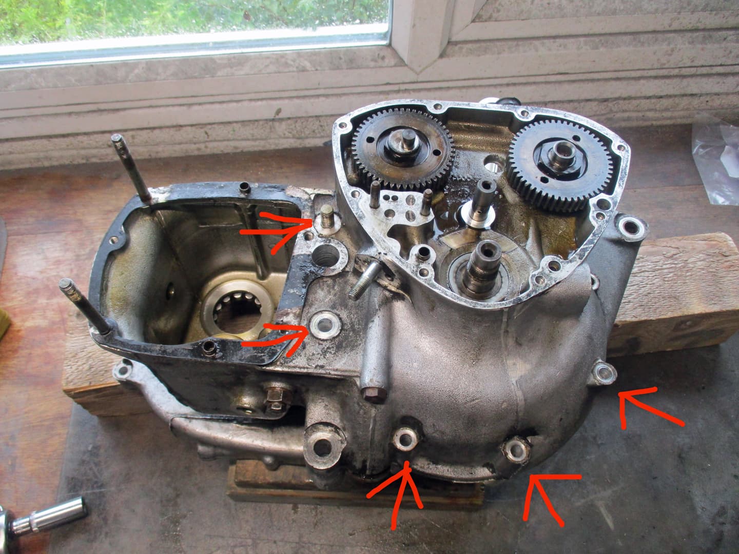
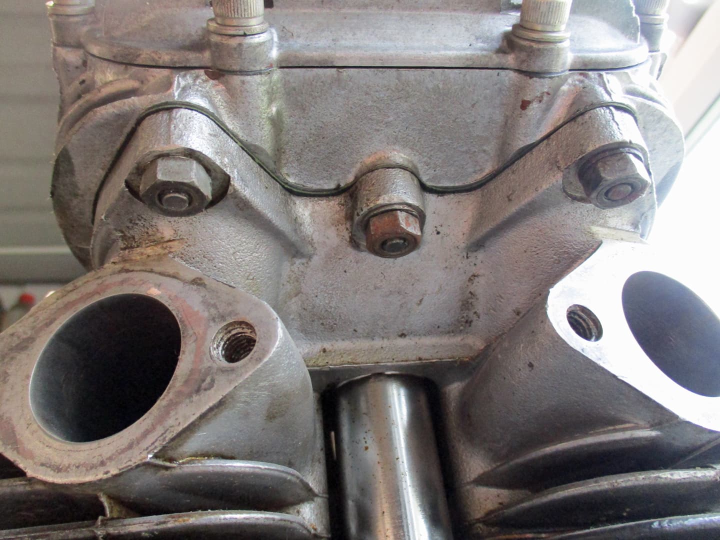
The same view looking up from the exhaust (front) side. The studs and nuts have been replaced with allen bolts. Obviously someone’s been in here but why replace the studs when lost nuts are easily replaced.

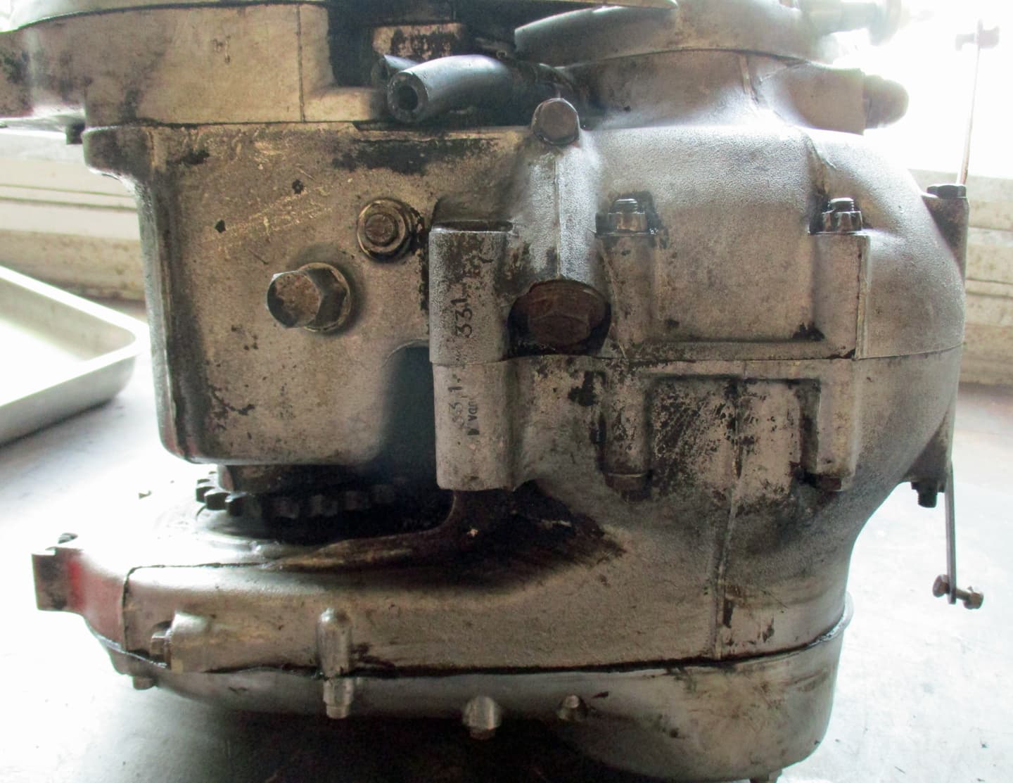
The bottom of the engine. Each casing has a number stamped on the engine mount boss. In this case 331 on both sides which shows that the cases are matching. I’ve had mismatched cases that fit perfectly so if there’s no massive oil leak, why not.
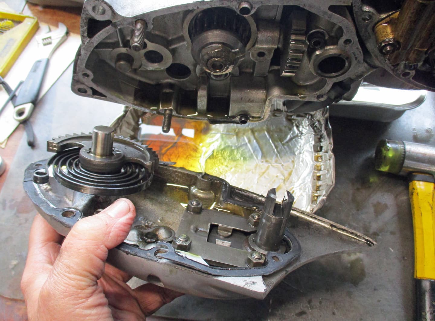
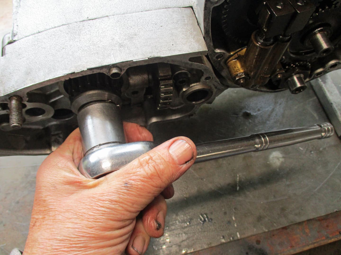
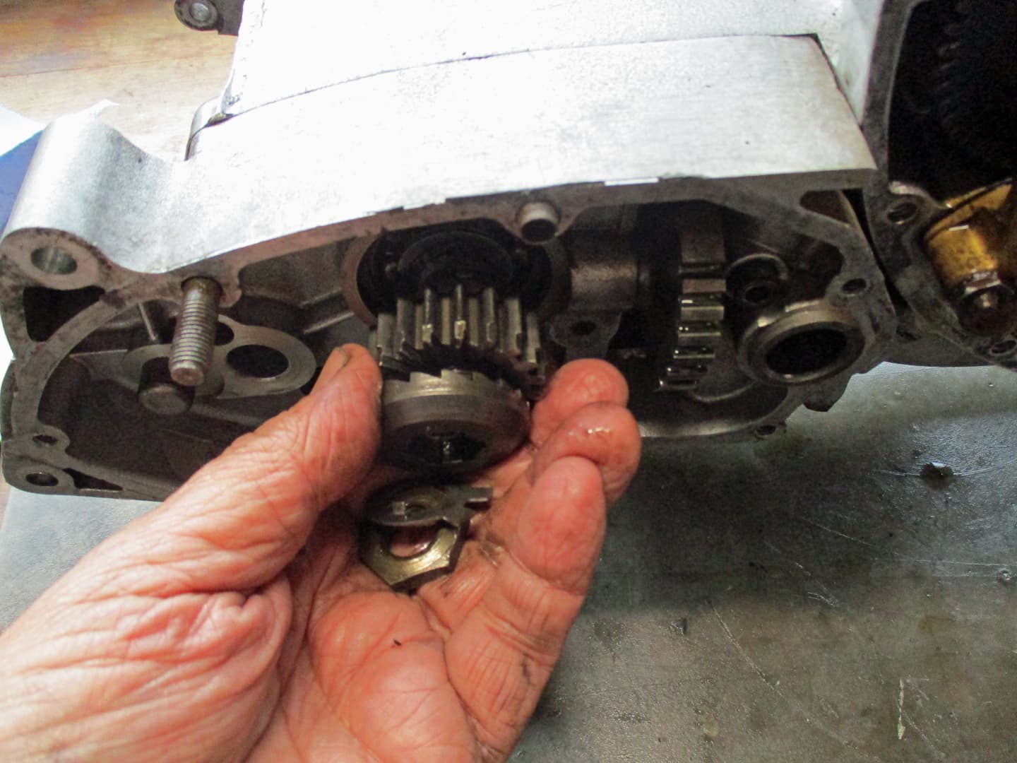
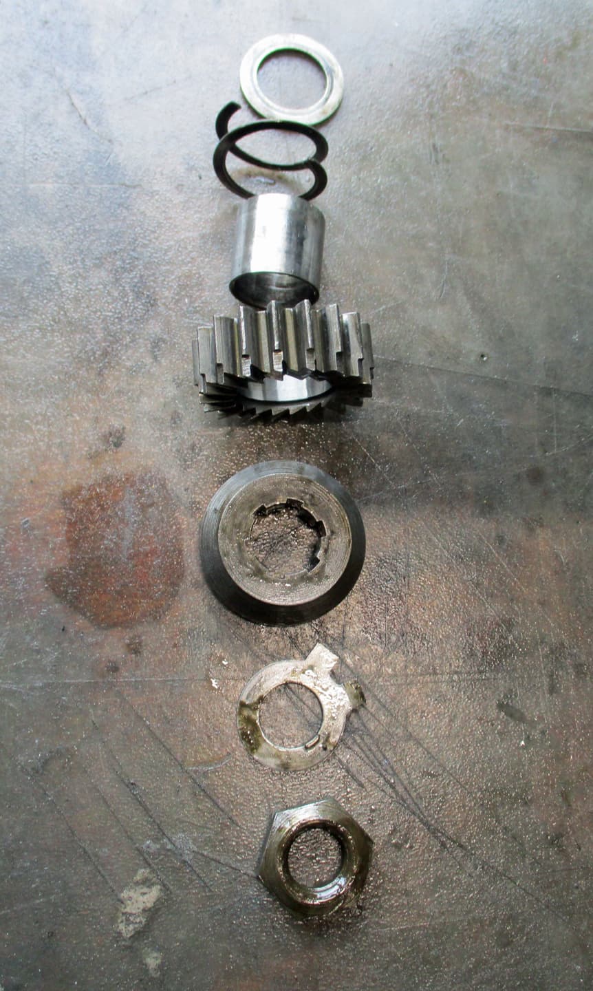
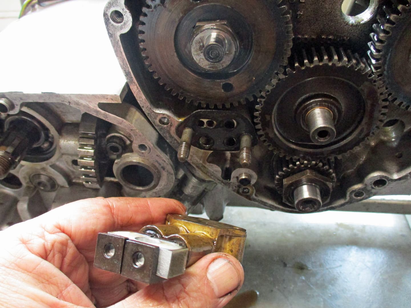
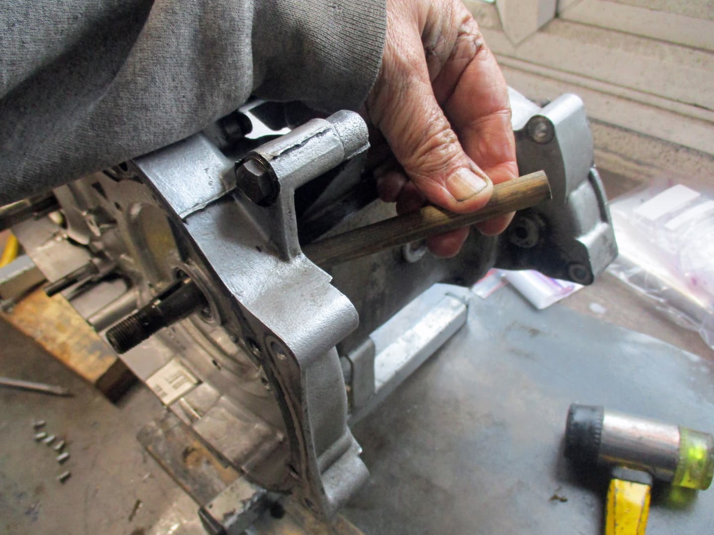
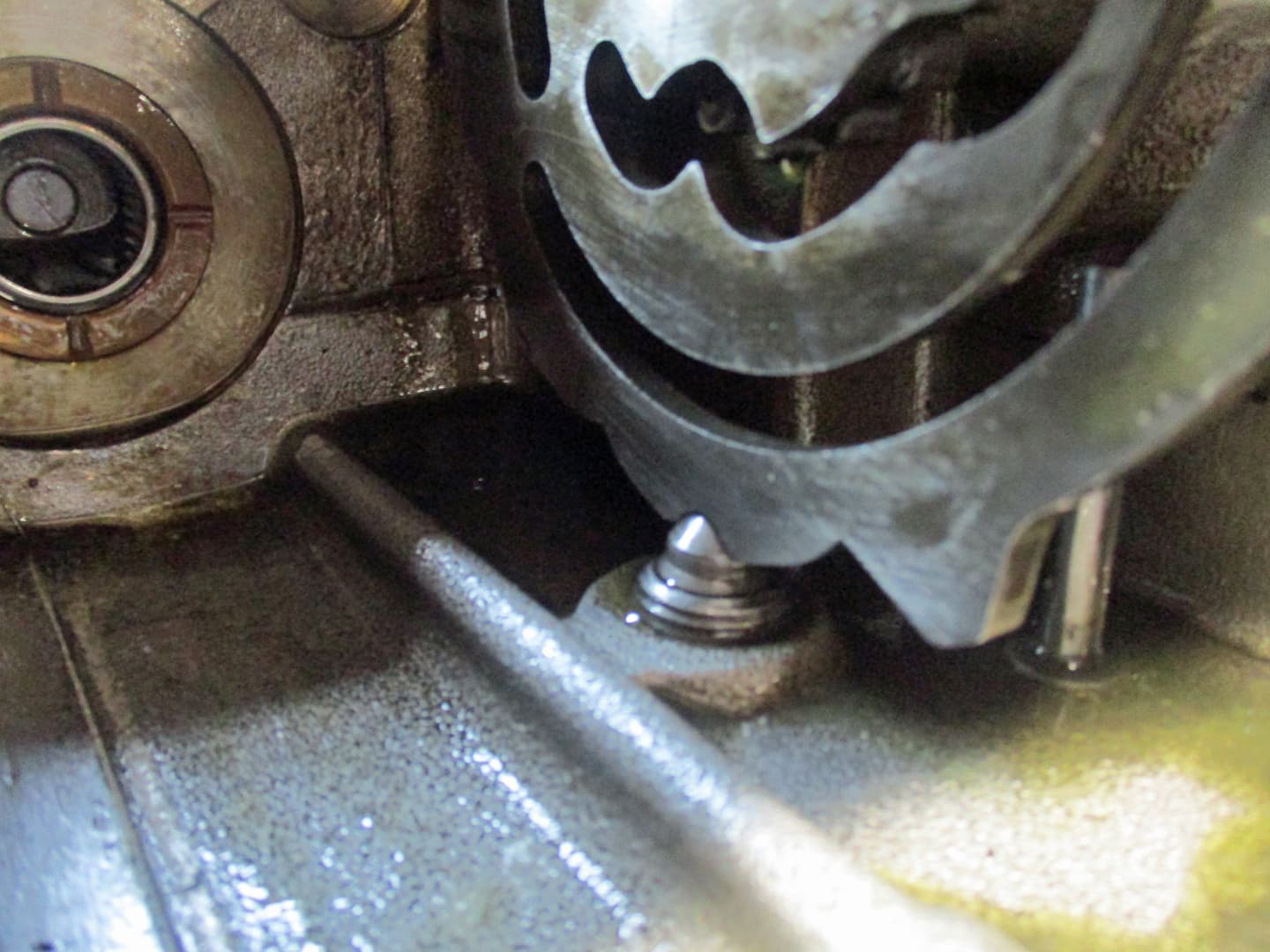
The large deep hex on the left under the gearbox is the housing for the detent plunger that holds the camplate in gear.
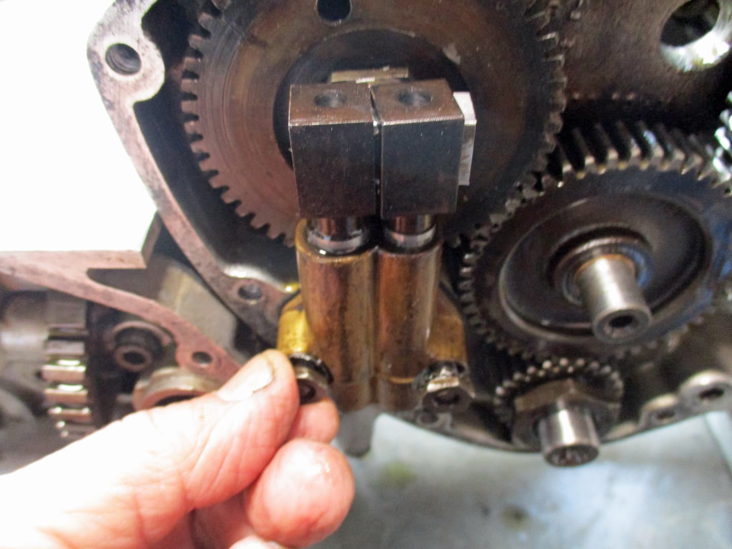
The smaller ‘twin’ hex just to the right and up from it, is the gearbox fill level tube and gearbox oil drain bolt.
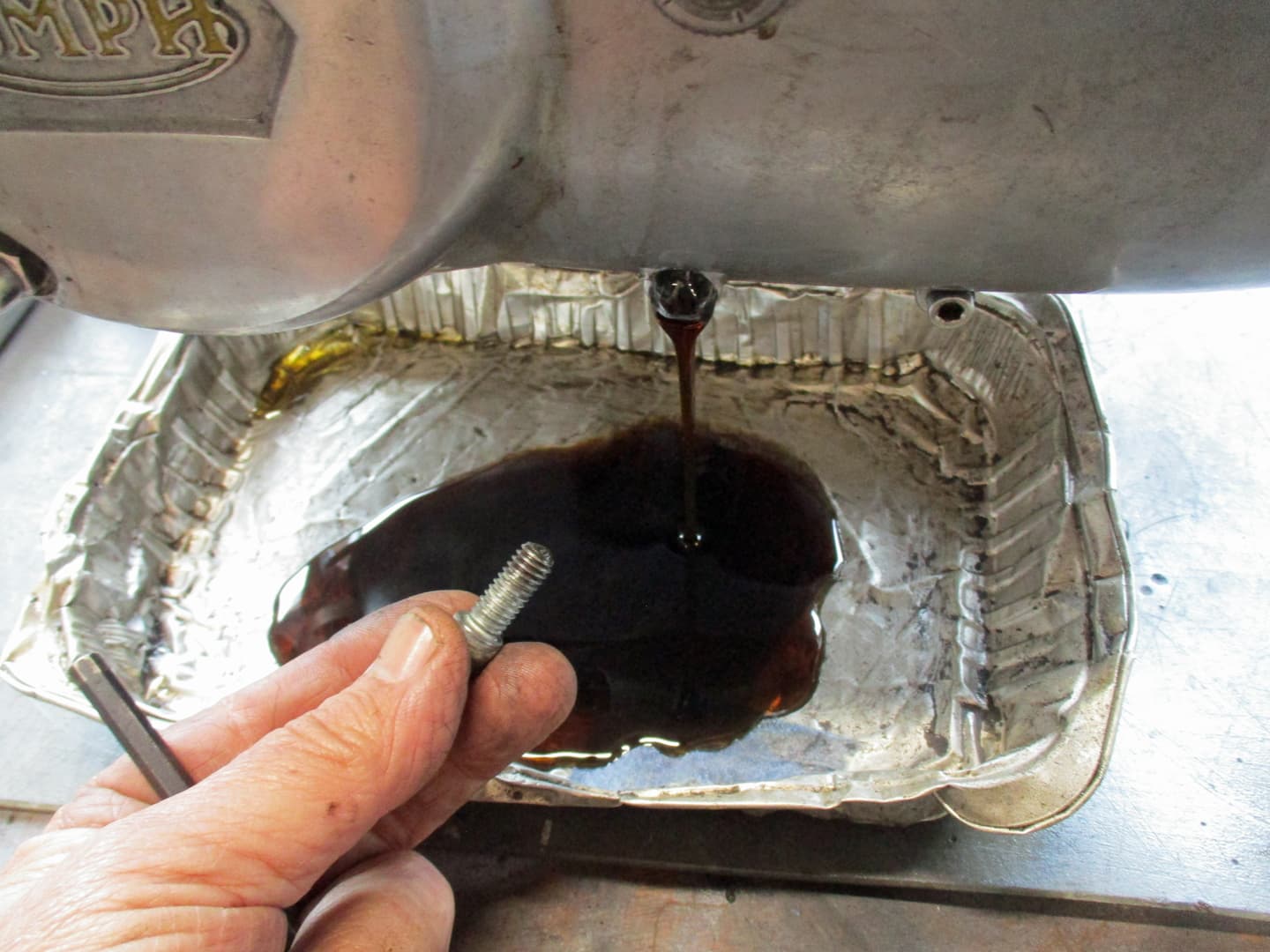
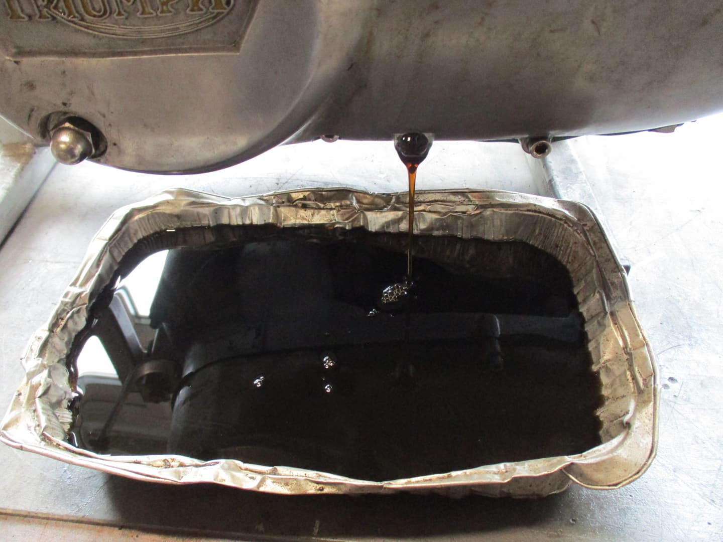
The large rusty looking hex nut on the other side of the engine mount boss is the sump drain plug.
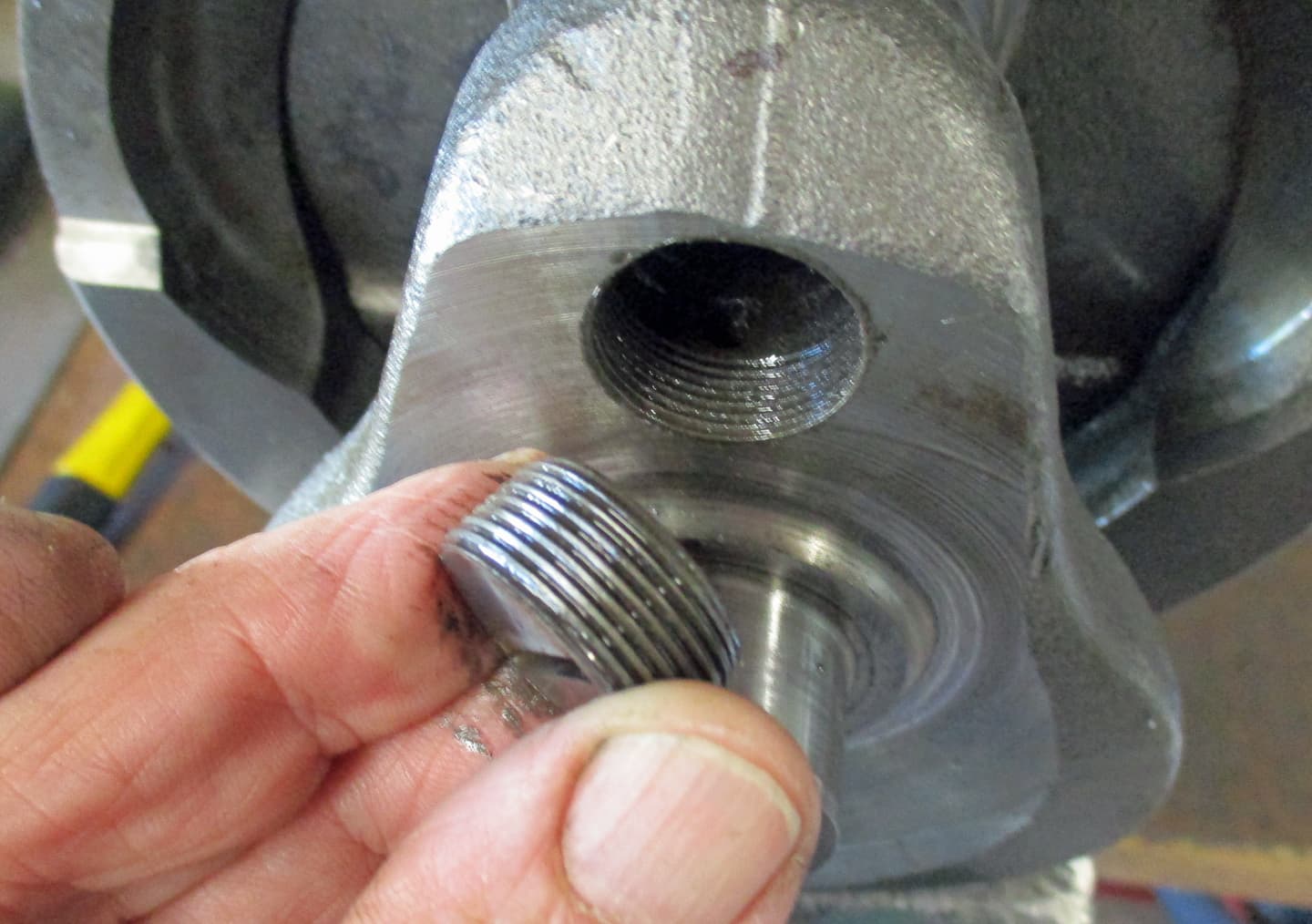
The smaller hex nut above the drain plug is a drilled oilway plug. This was to allow the engine manufacturers to drill an oilway through to the oil pump, it just stays plugged up with a bolt.
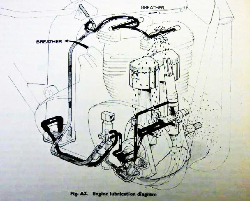
The two rubber hoses above that are the delivery and return hoses to the oil tank.
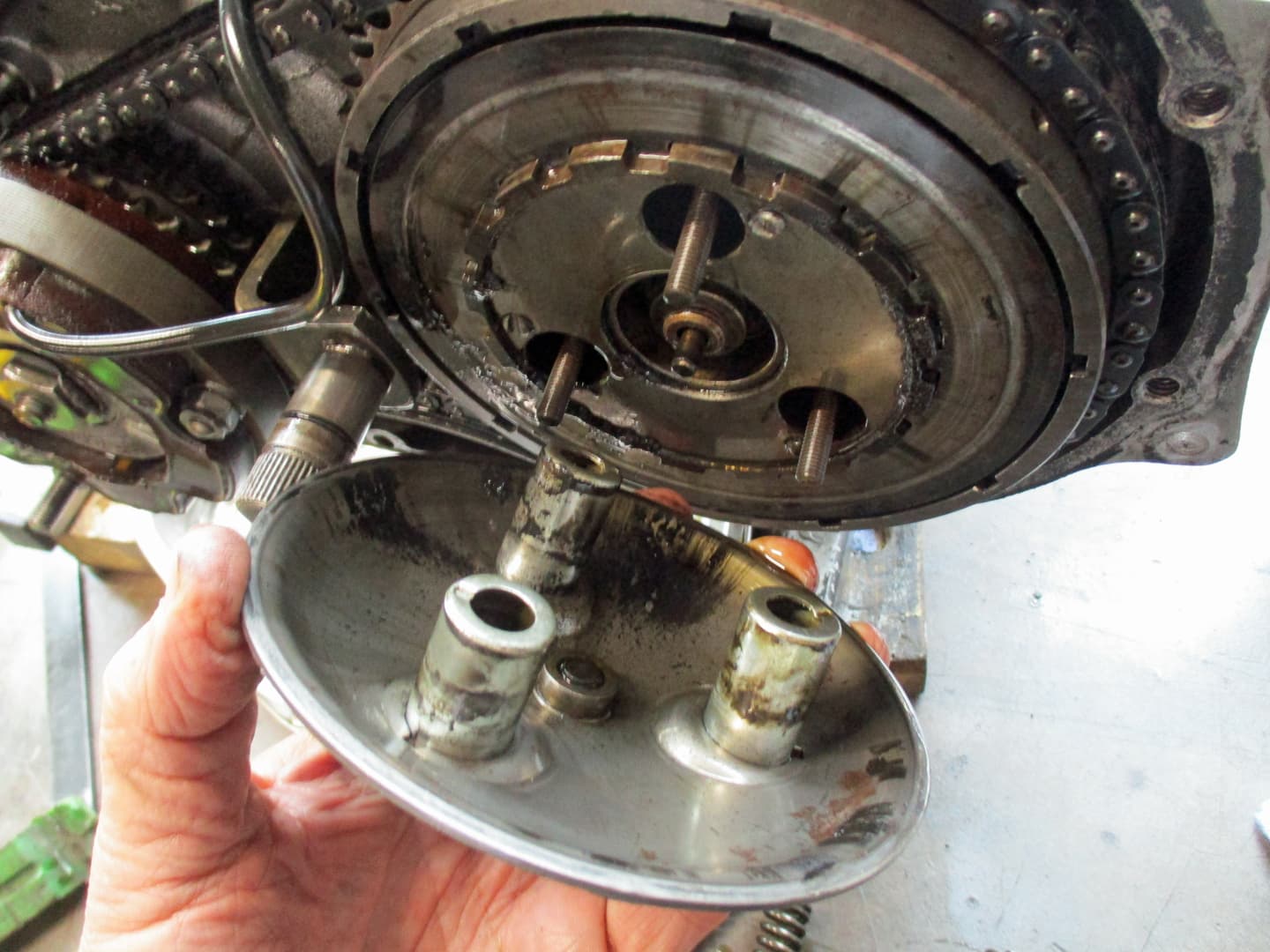
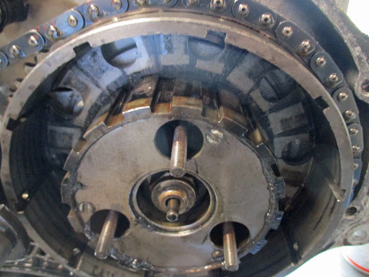
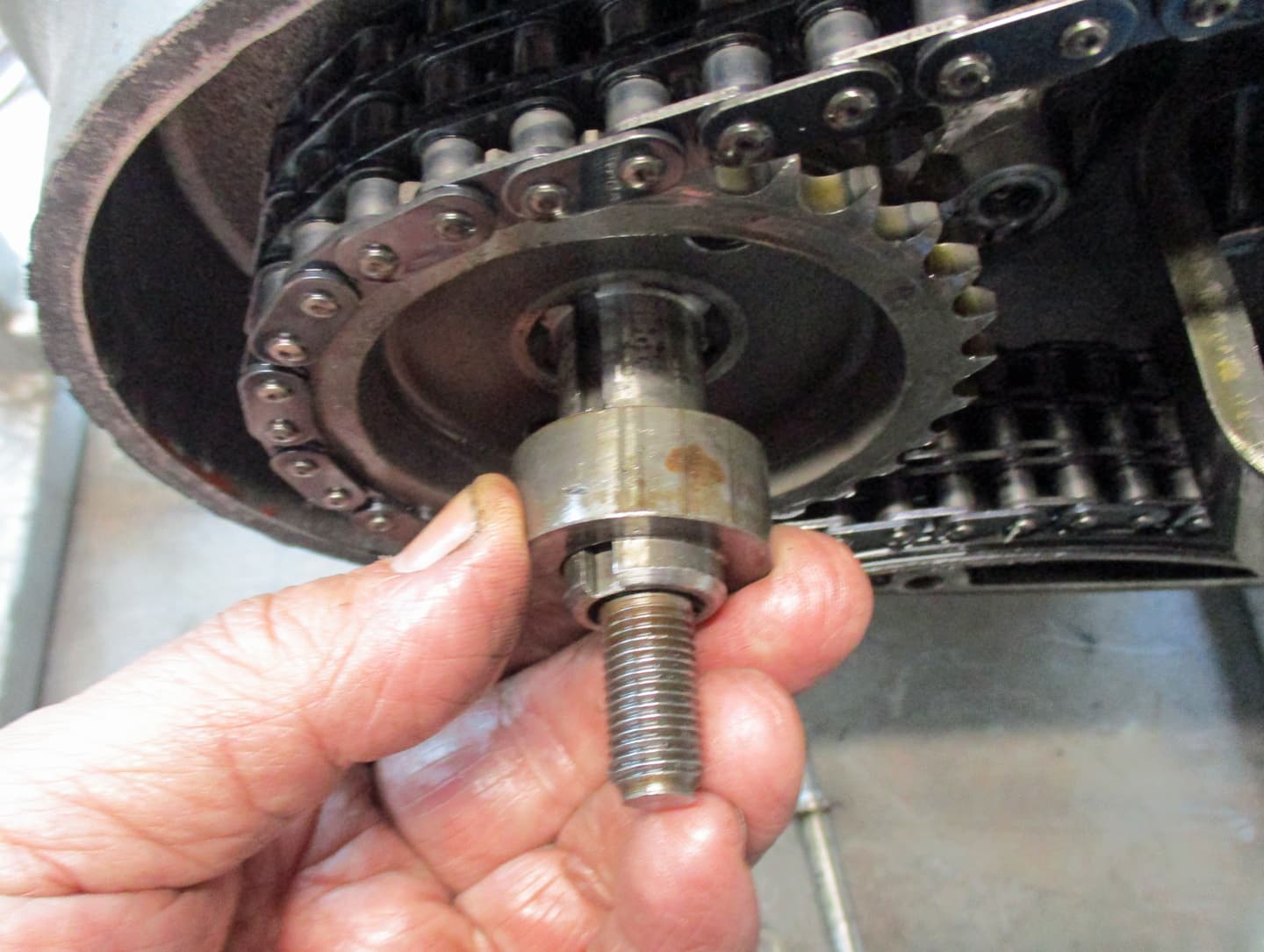
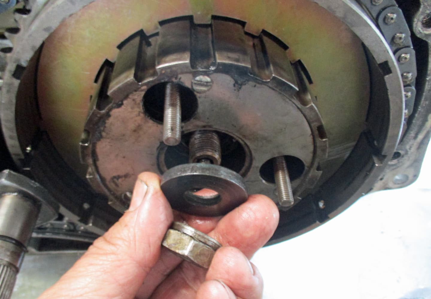
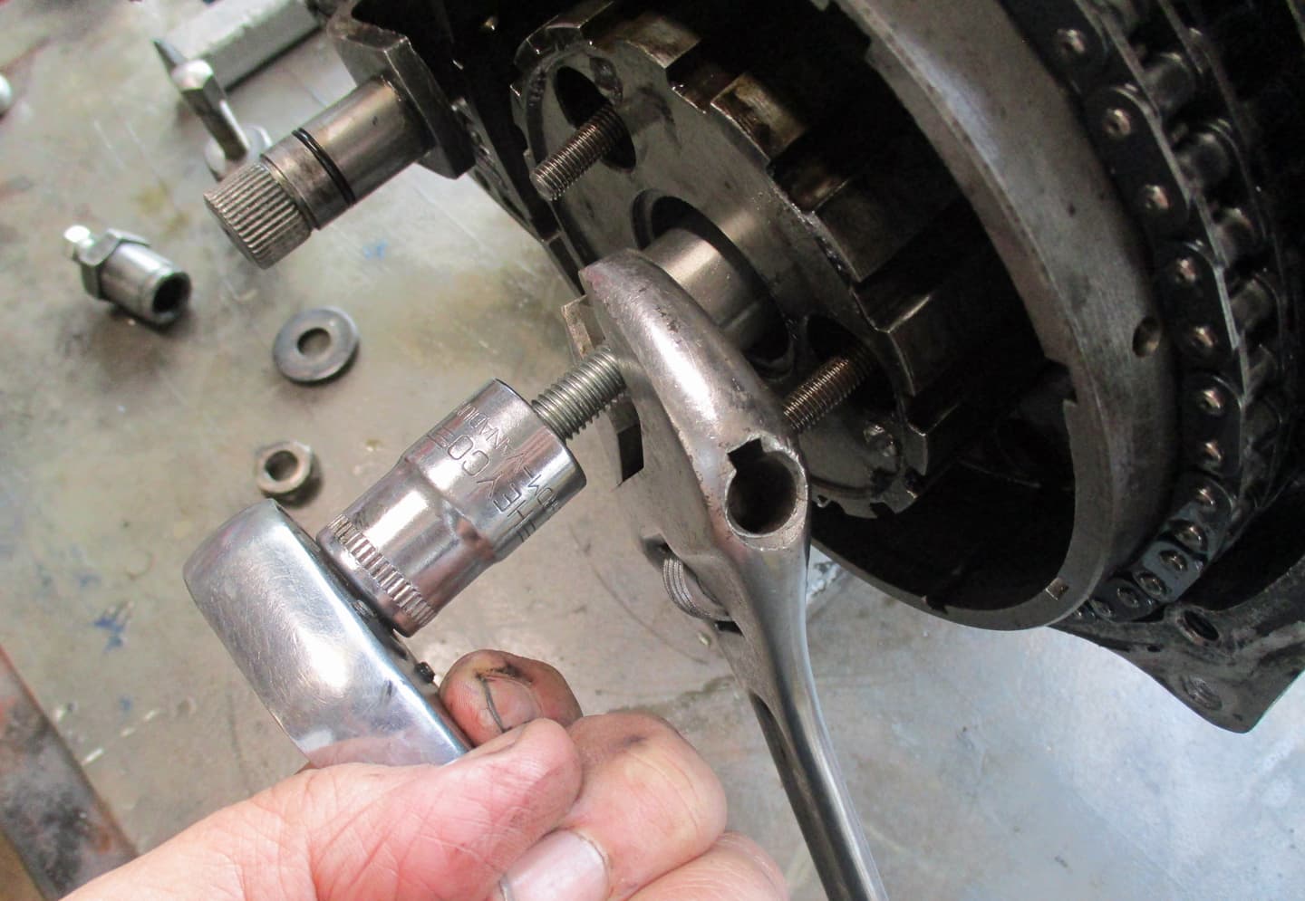
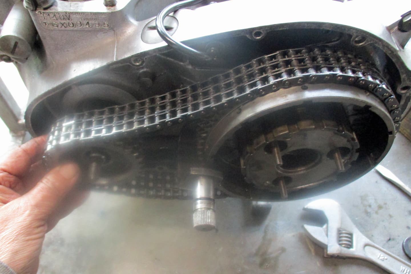
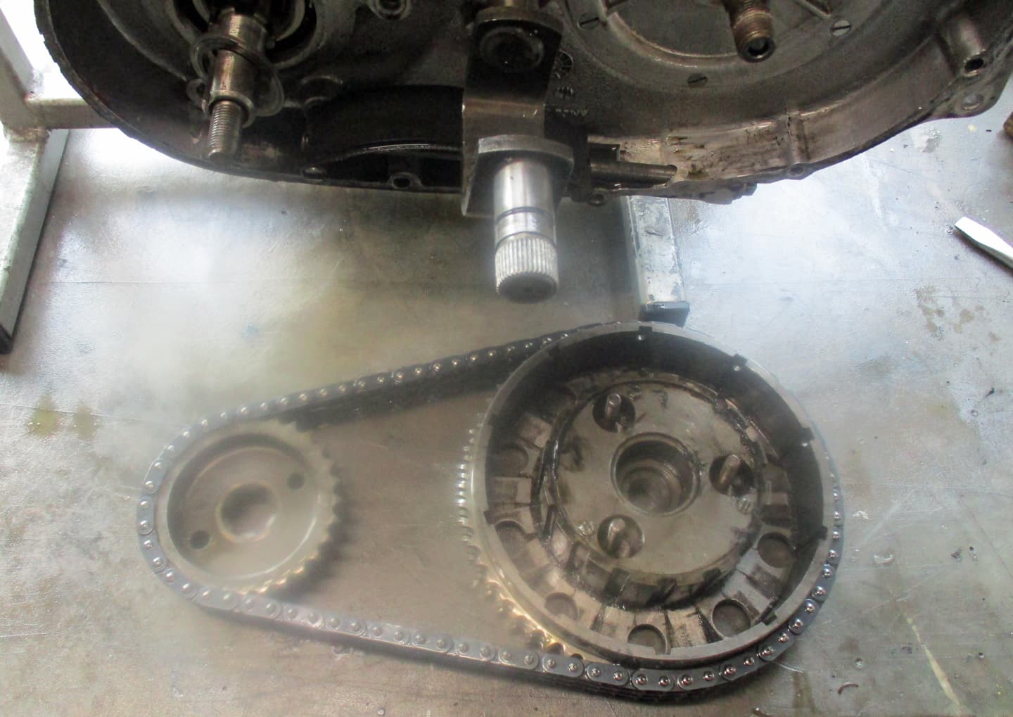
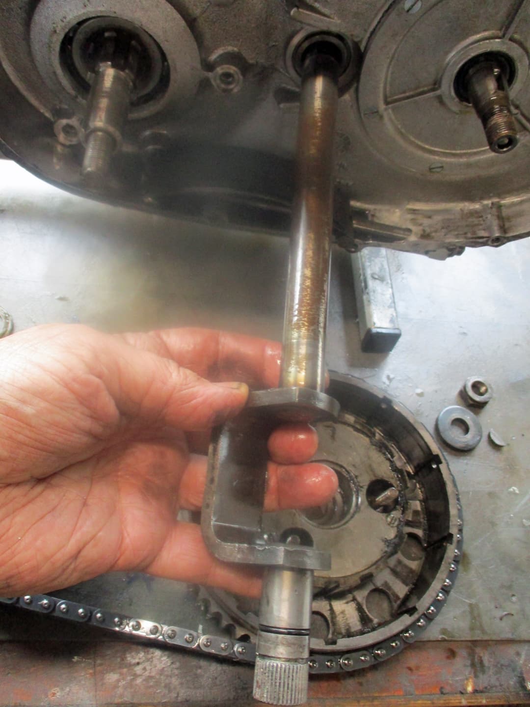
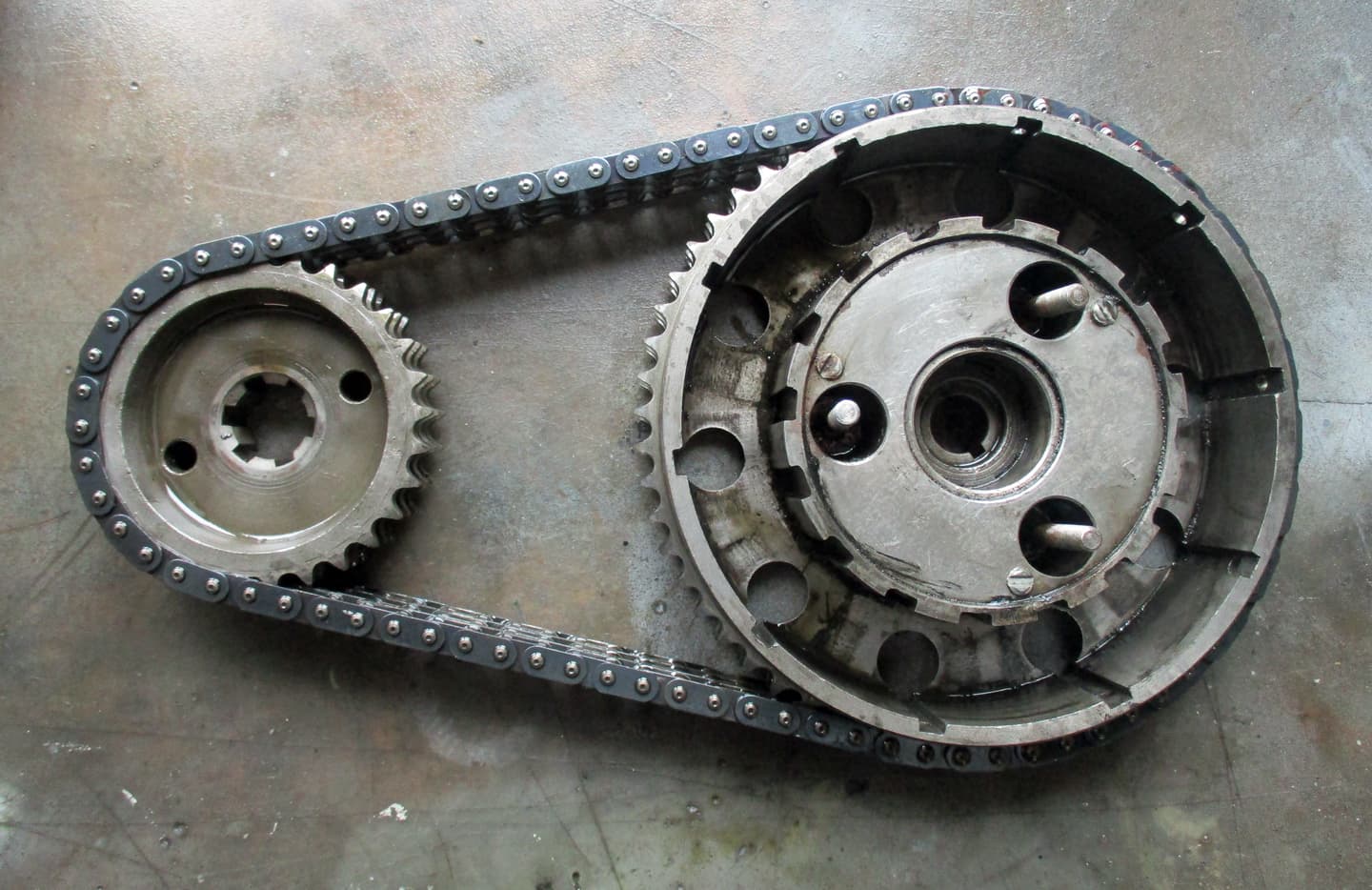
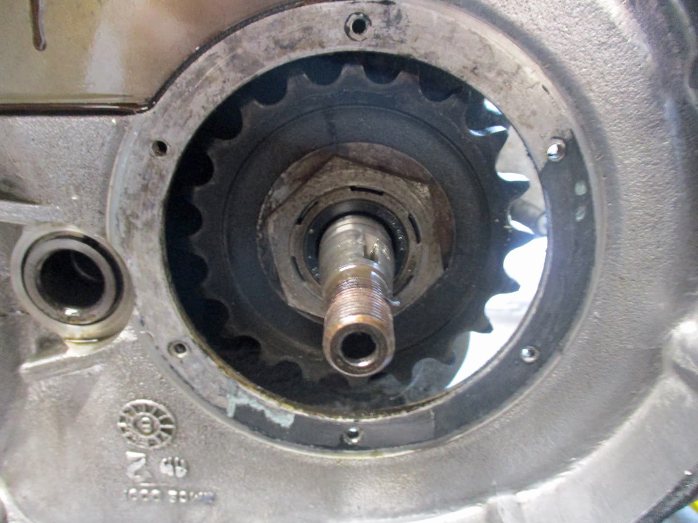
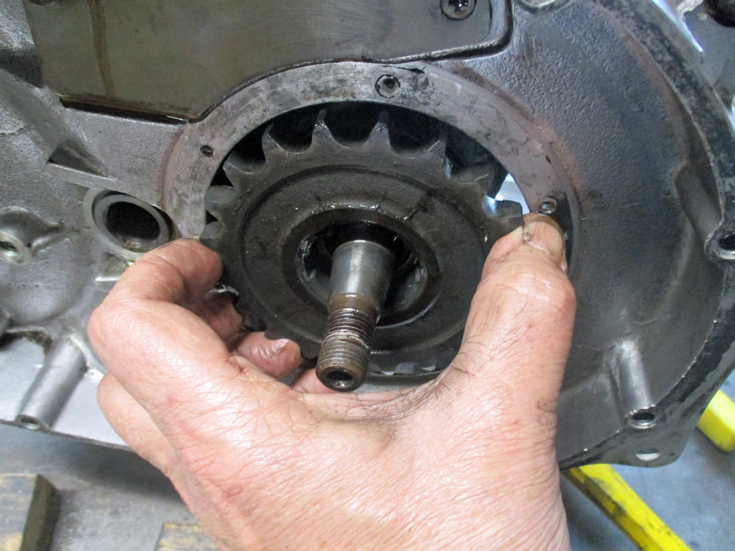
The sprocket seen below the gearbox is the front chain sprocket. It can only be removed with the clutch out.
All the other nuts are casing bolts as the casings are split vertically.

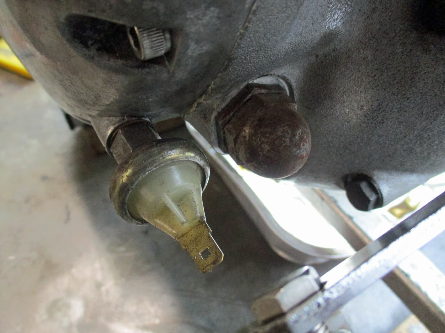
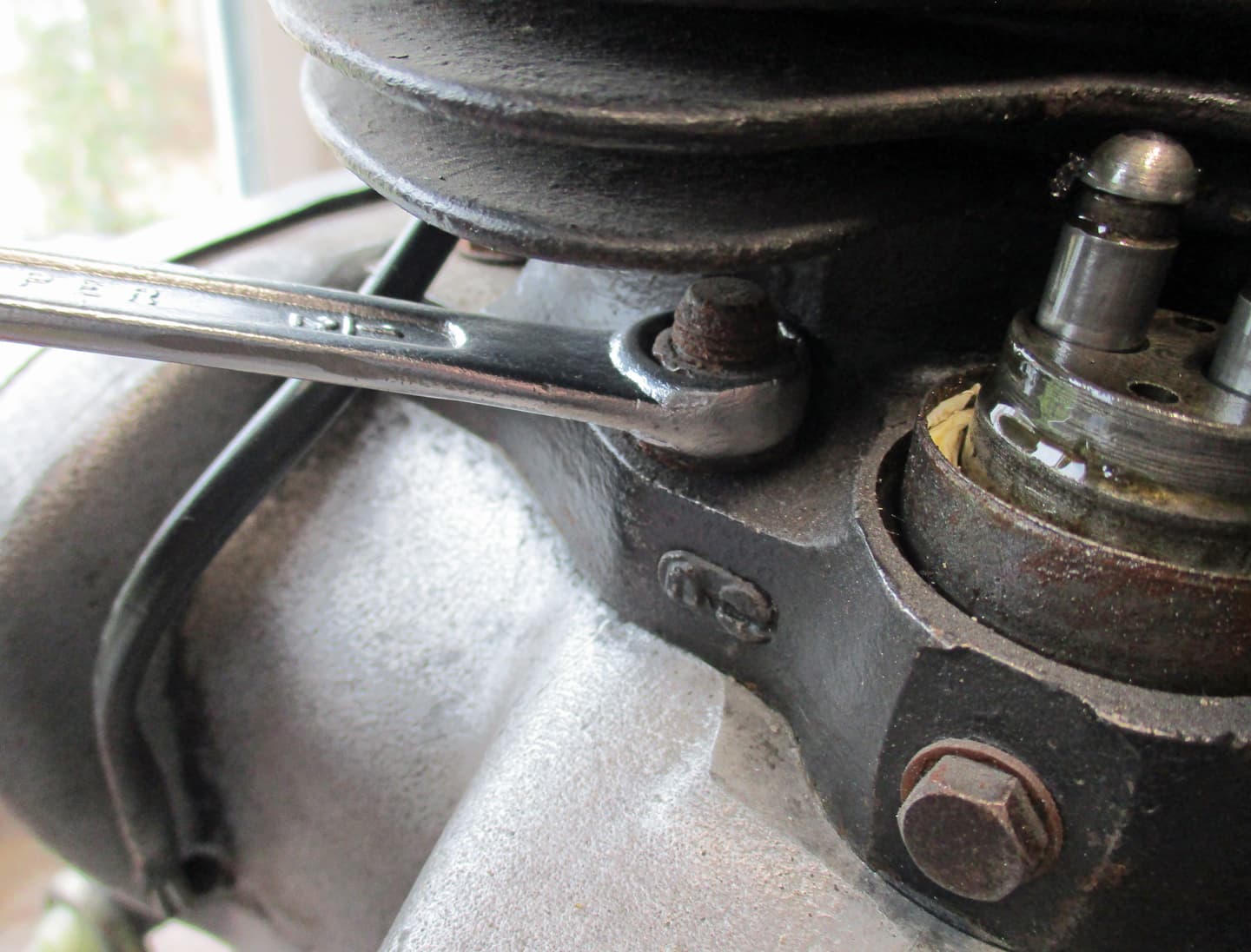
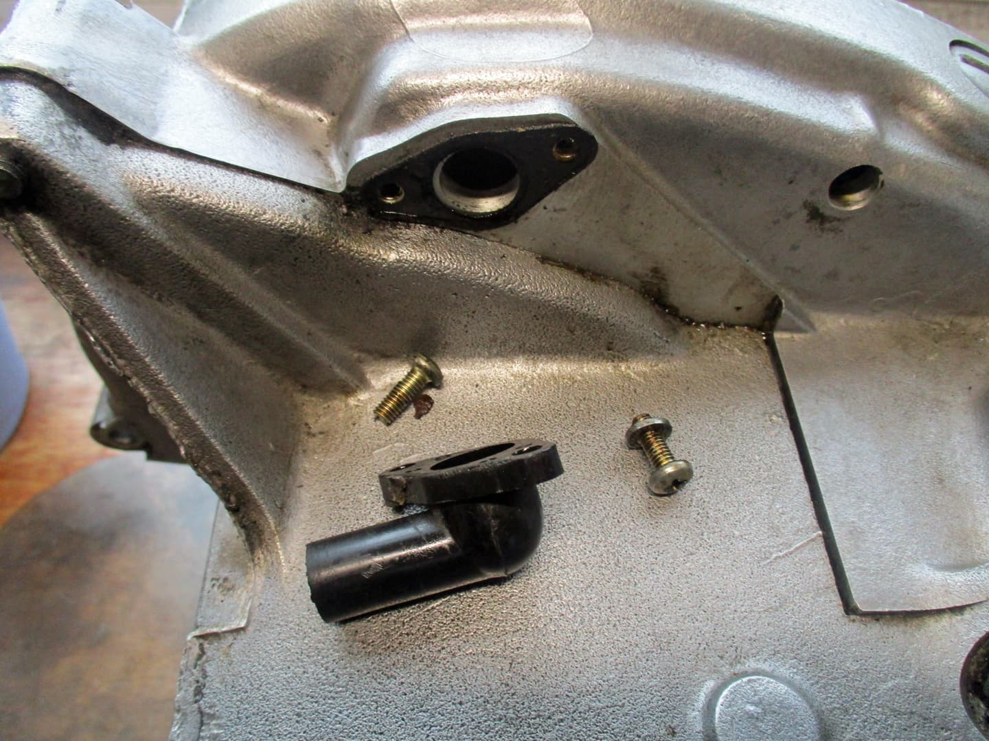
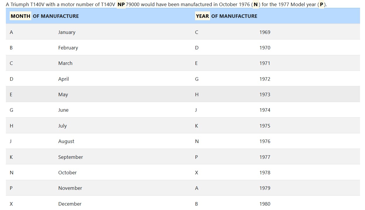
On the front right side of the engine is the oil pressure switch - a simple switch that turns on a light if the oil pressure falls. Some remove this and fit an oil pressure gauge to see the actual readings (I find having a gauge to watch can become a bit obsessive).
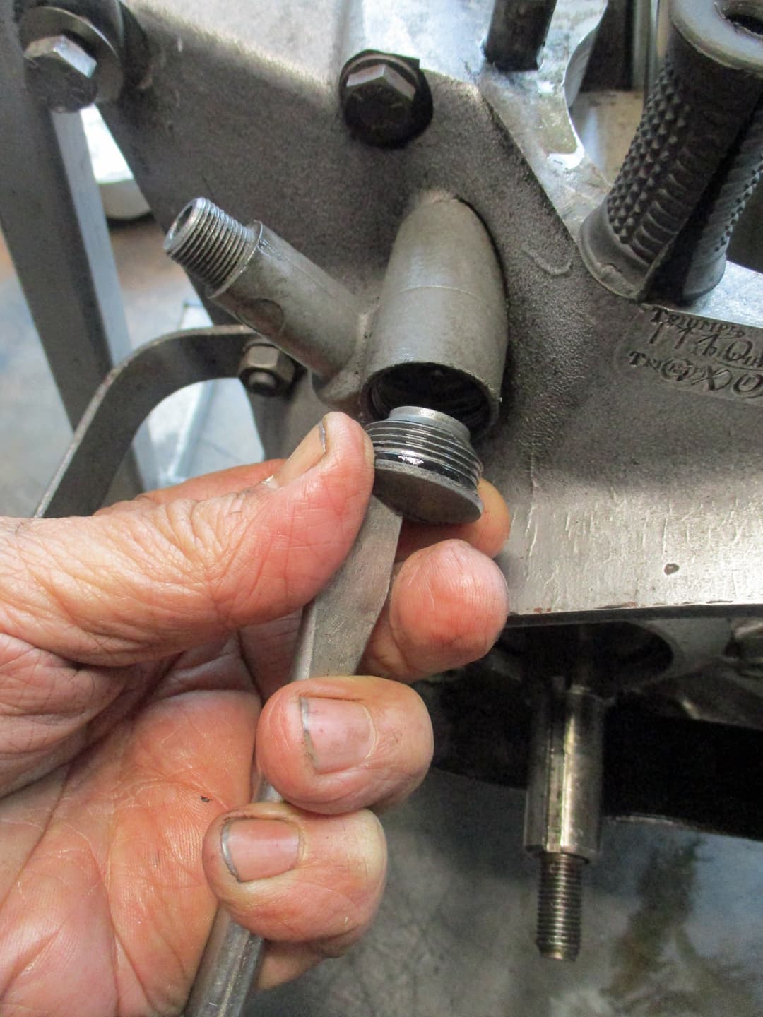
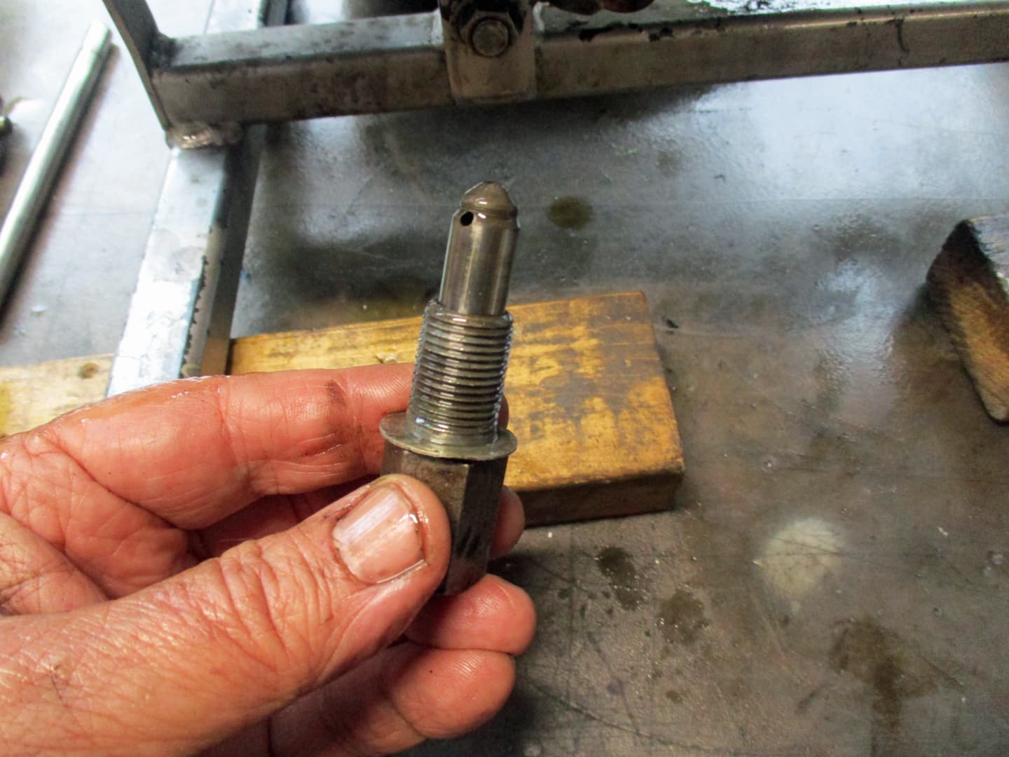
The rusty domed item is the pressure relief valve. This allows any excessive oil pressures to be relieved by allowing oil to pass directly into the sump bypassing the normal route through the crankshaft. This will usually operate when the engine is cold as the oil is generally thicker untill it heats up. I’ll show how it works when it’s dismantled later on.

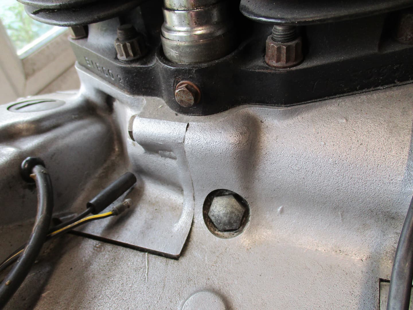
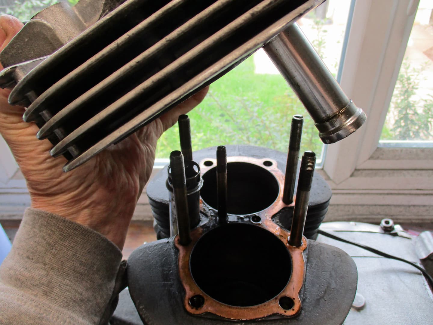
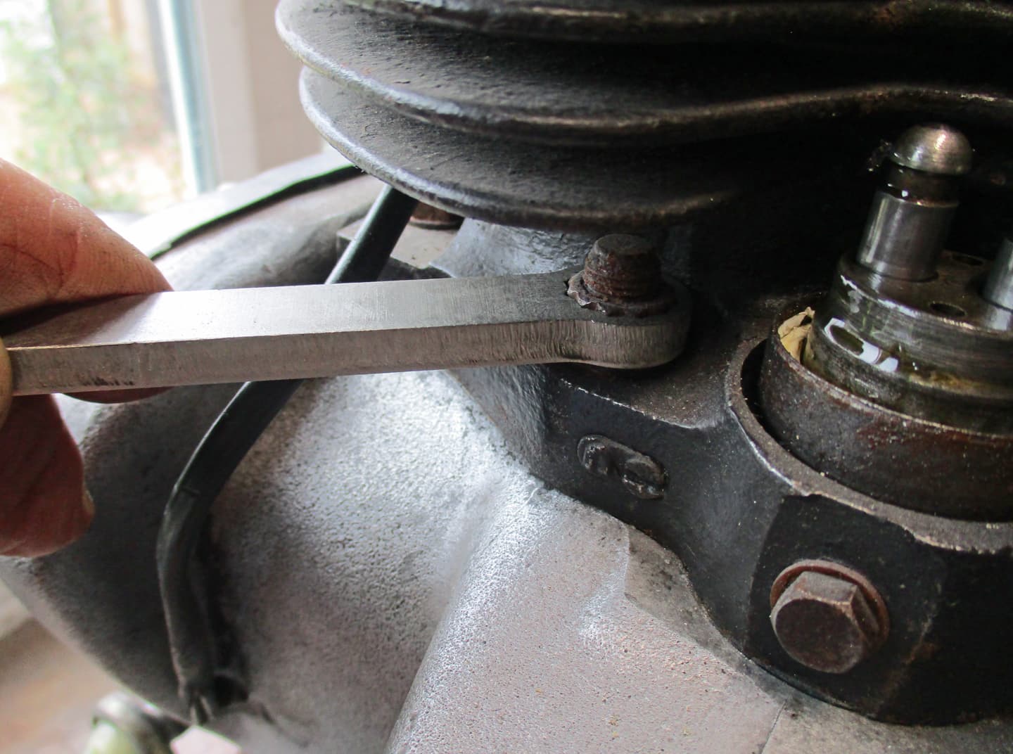
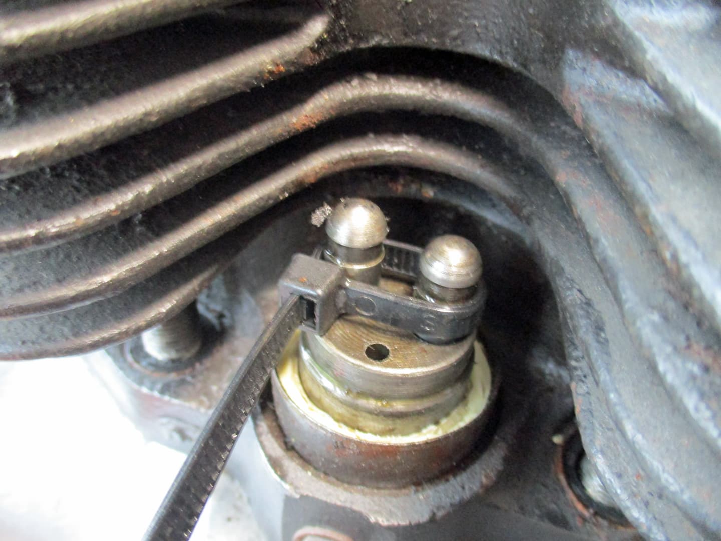
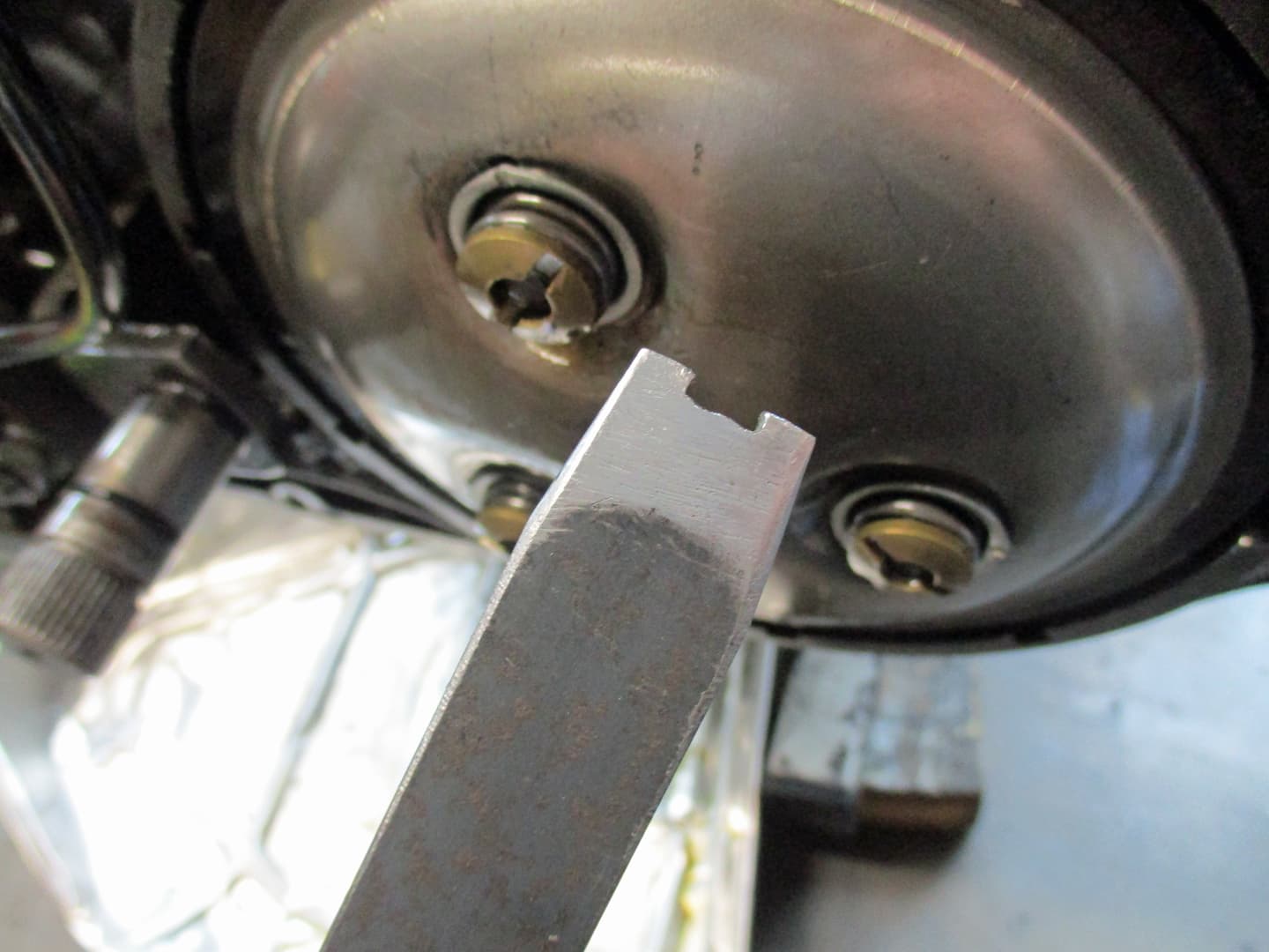
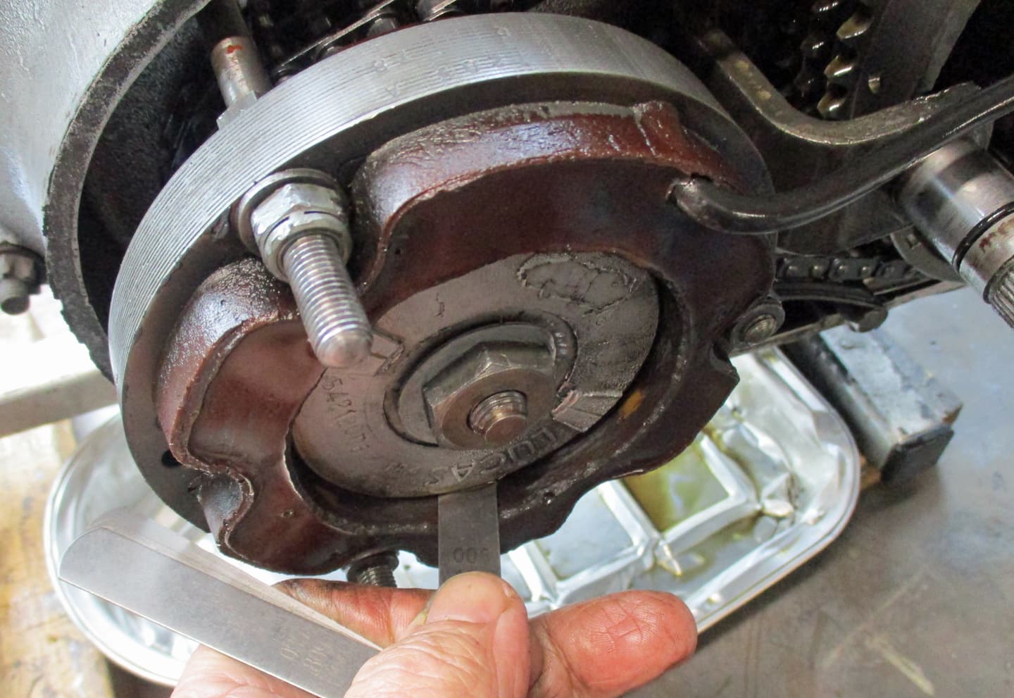
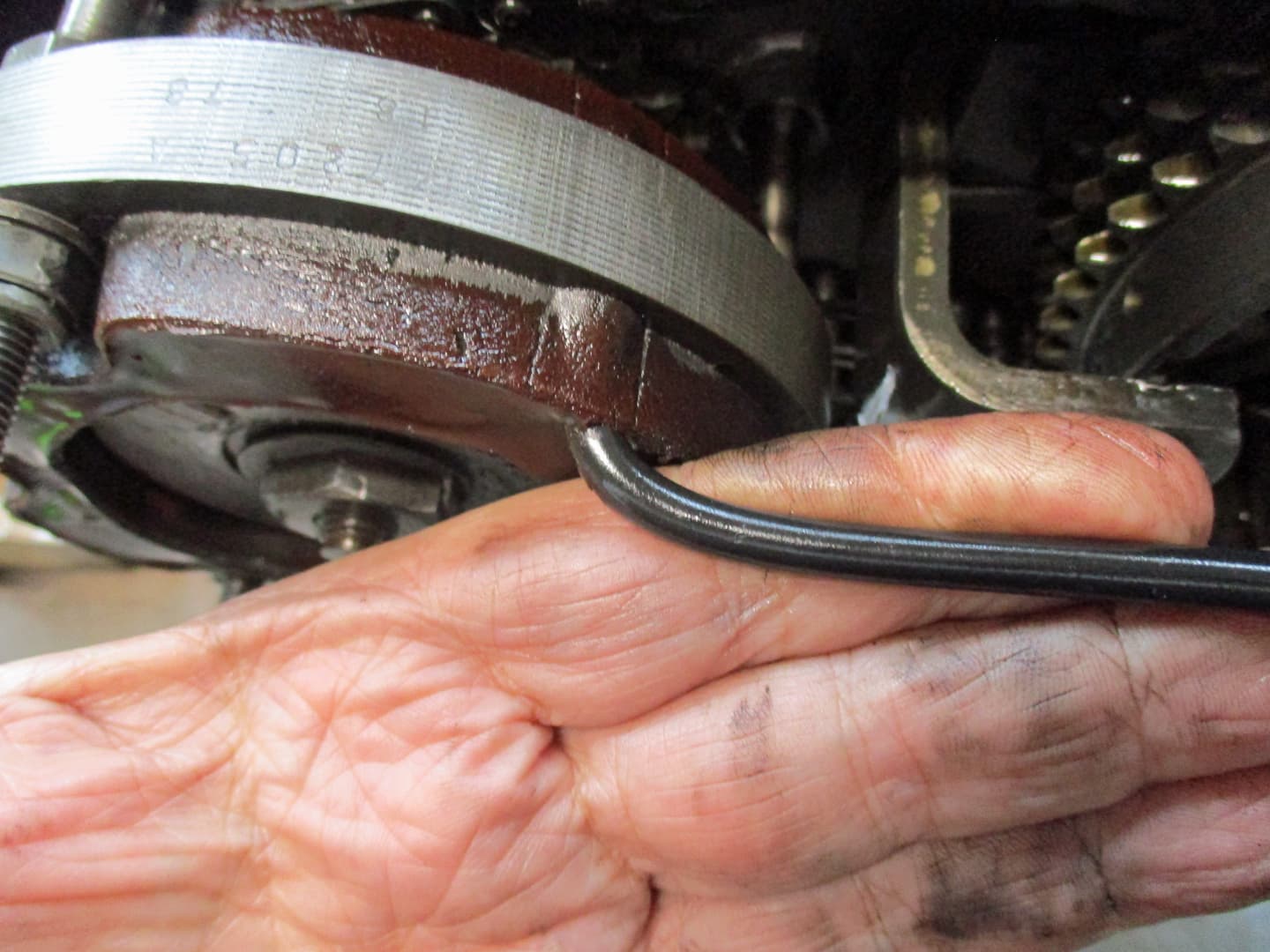
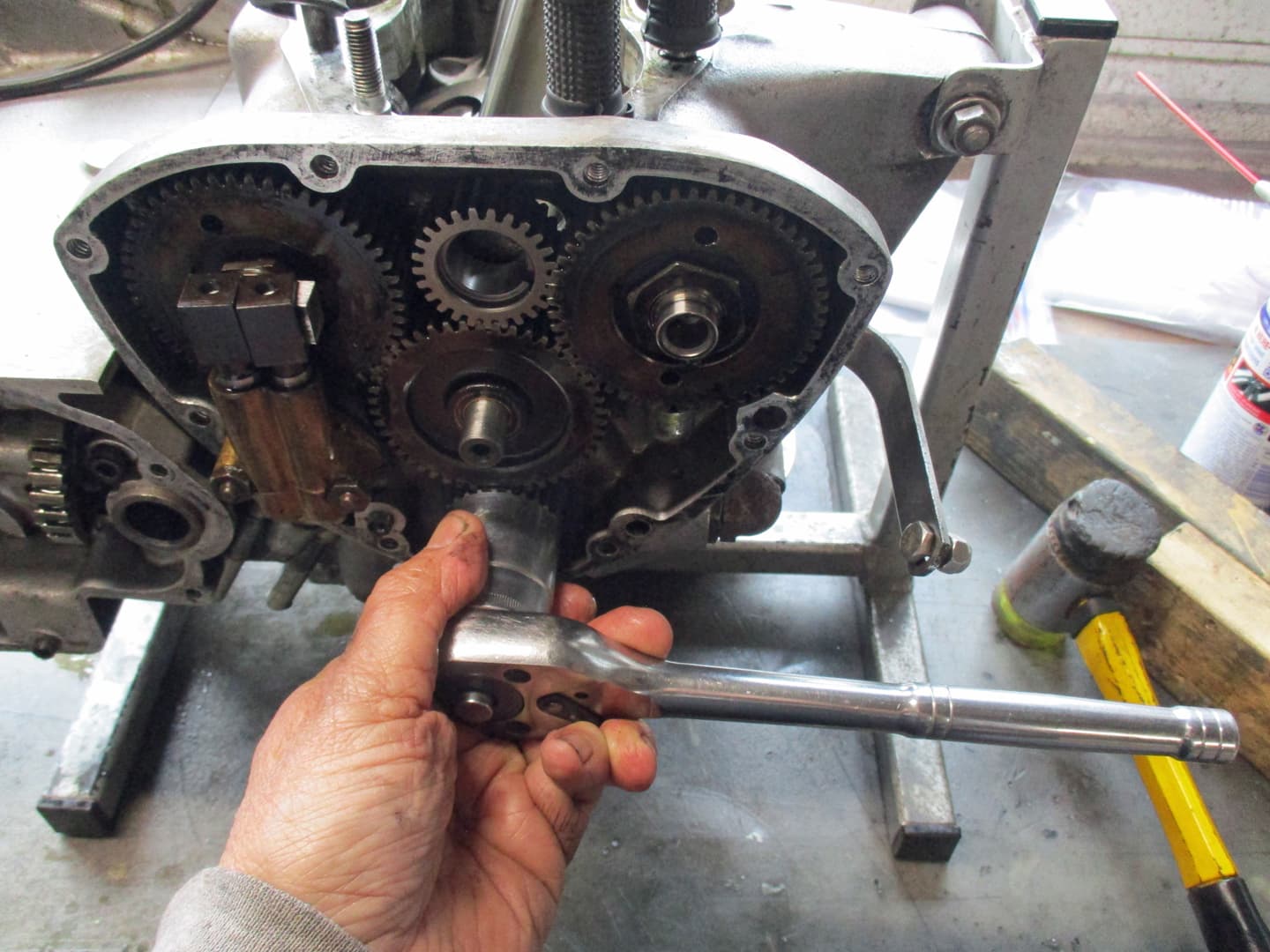
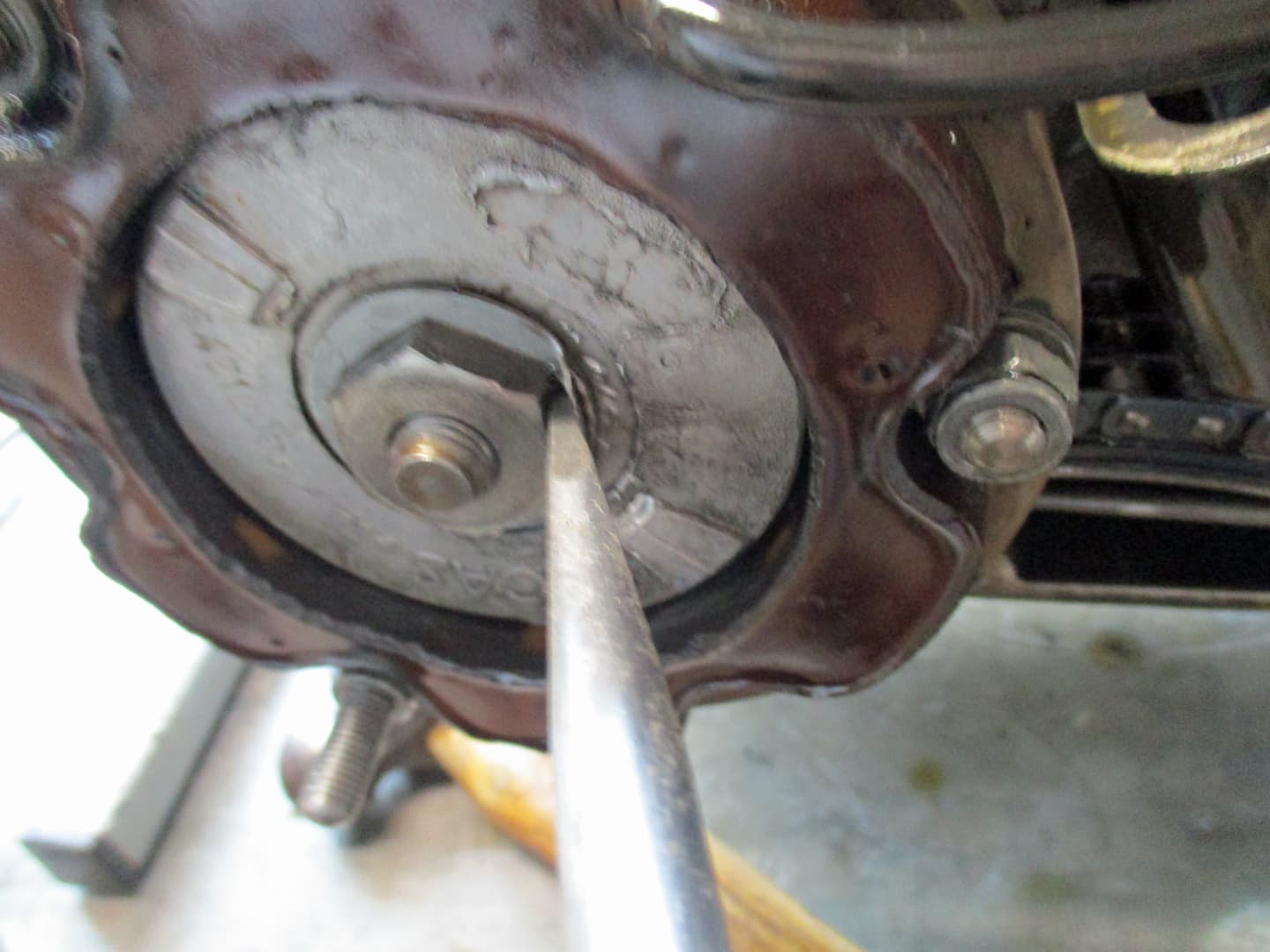
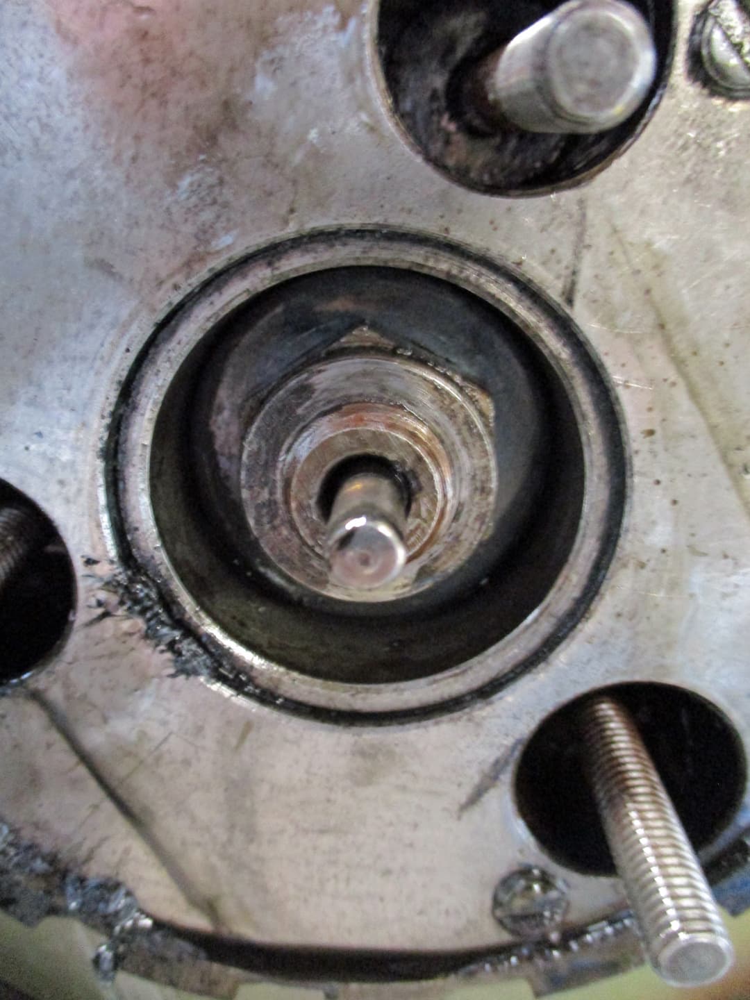
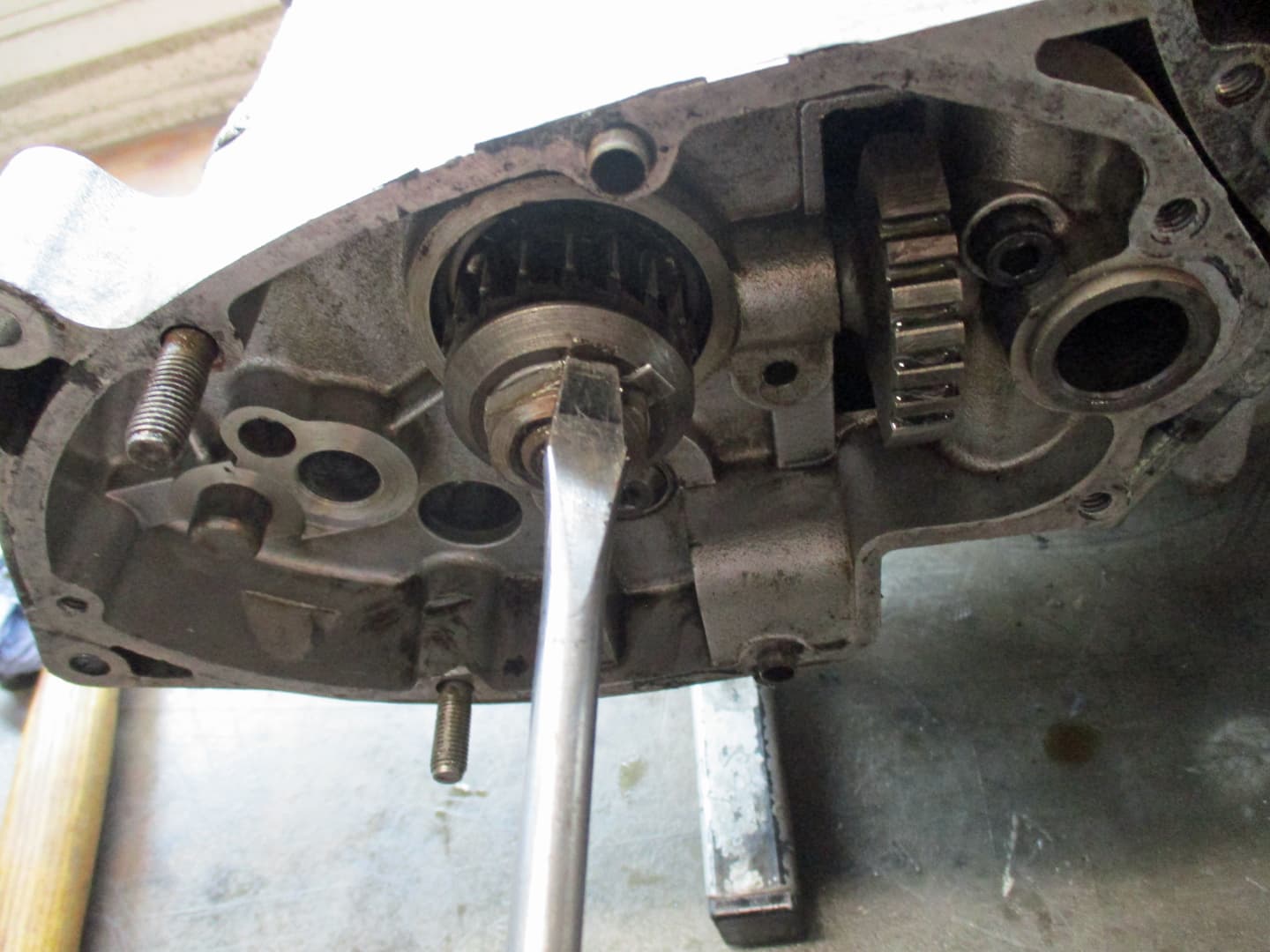
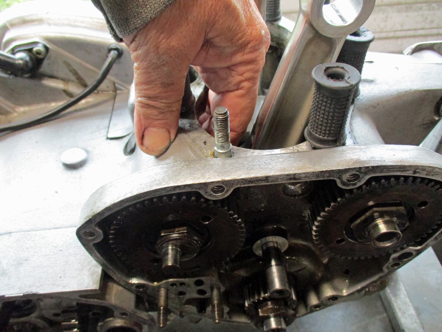
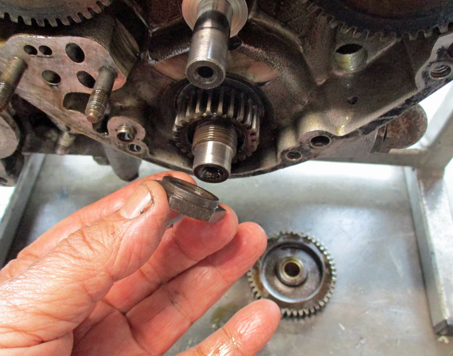
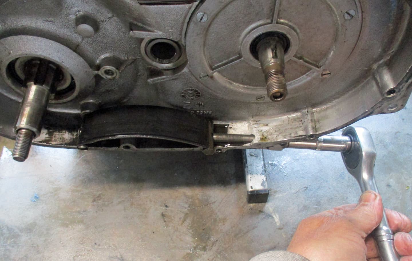
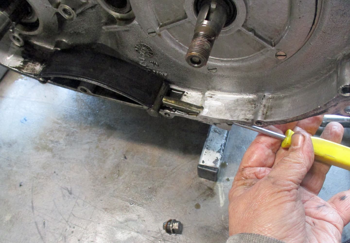
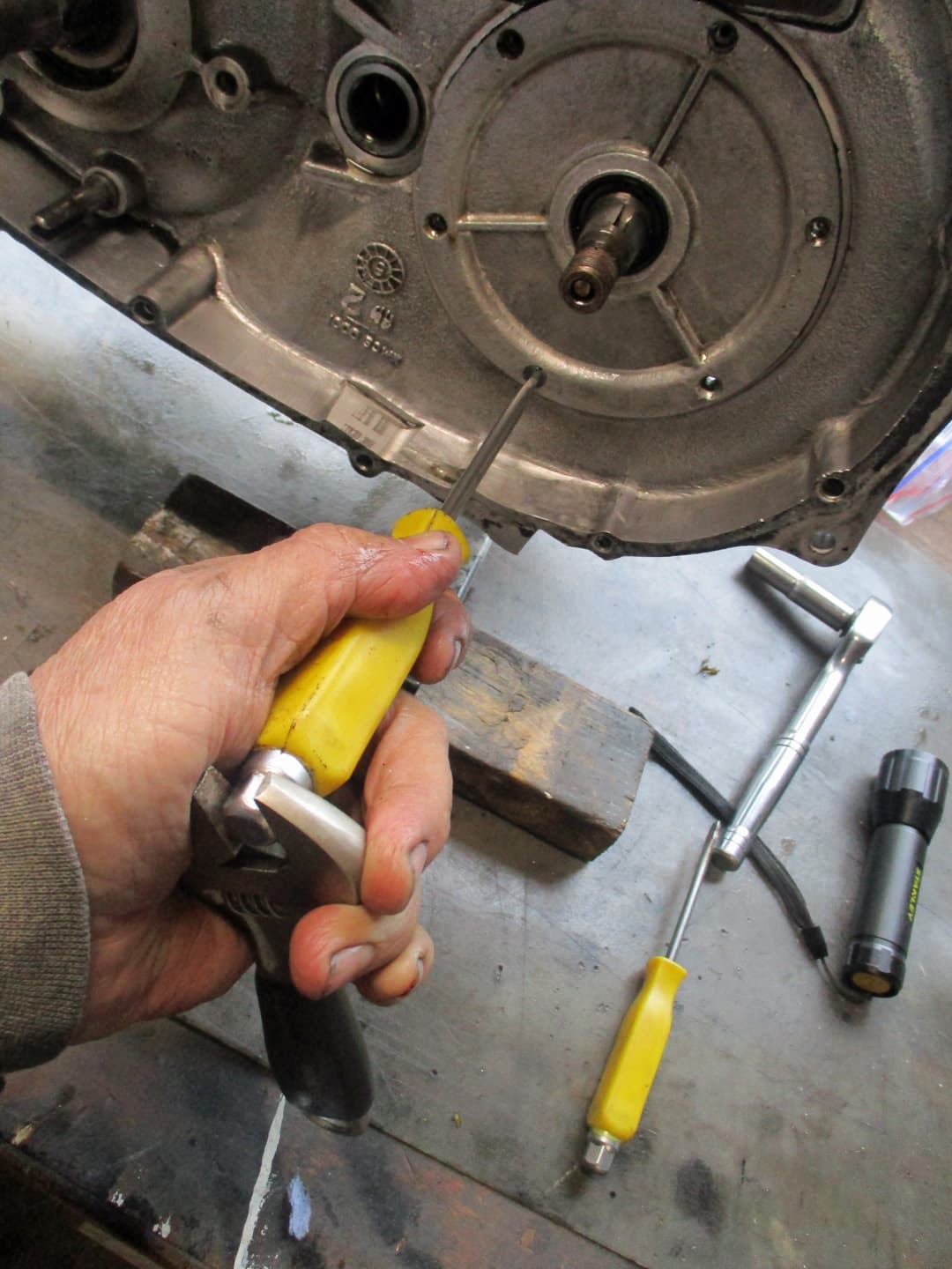
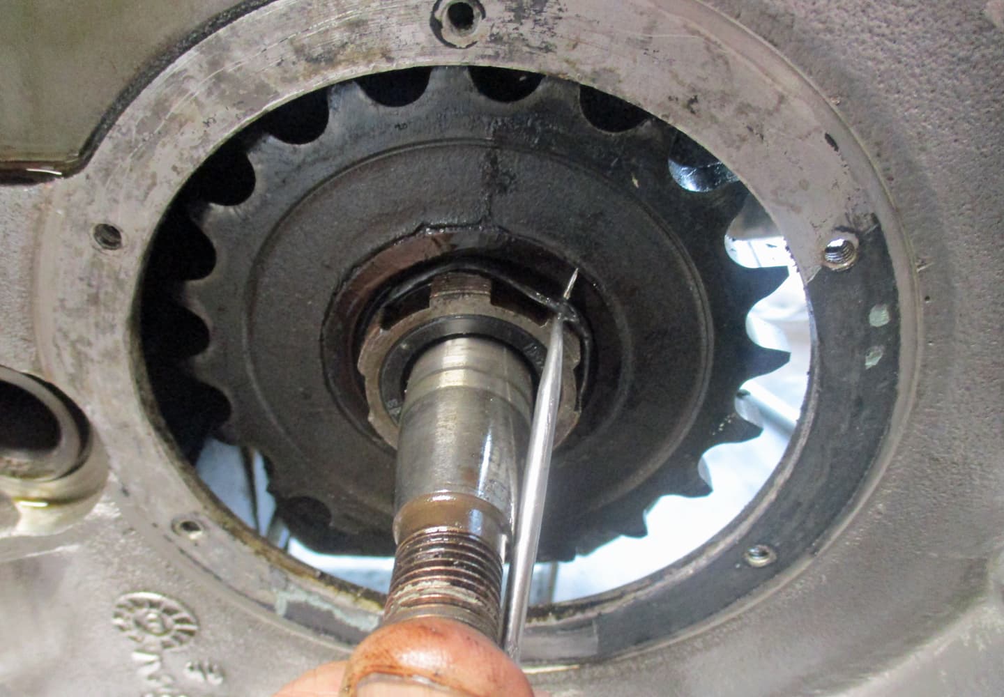
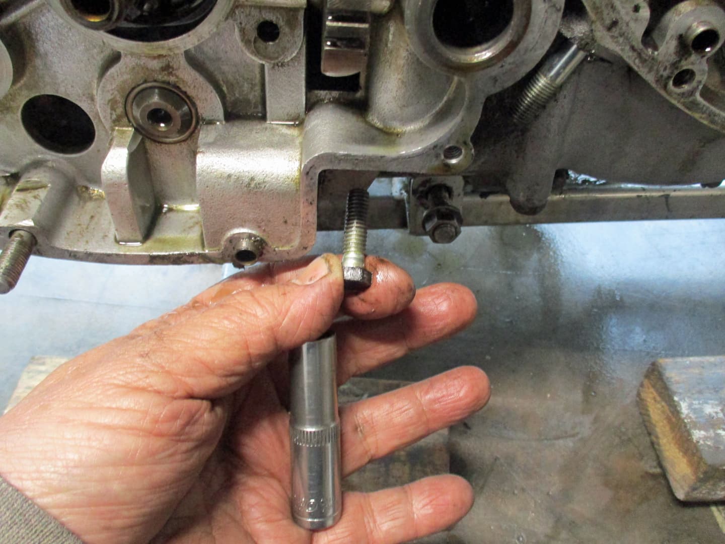
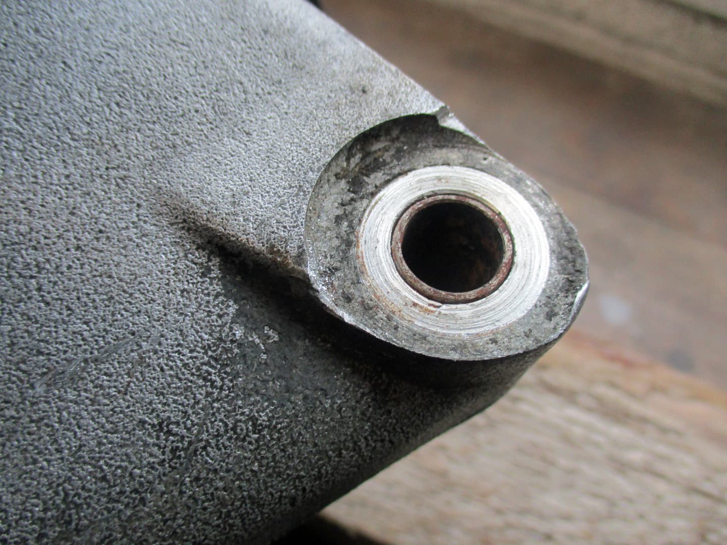
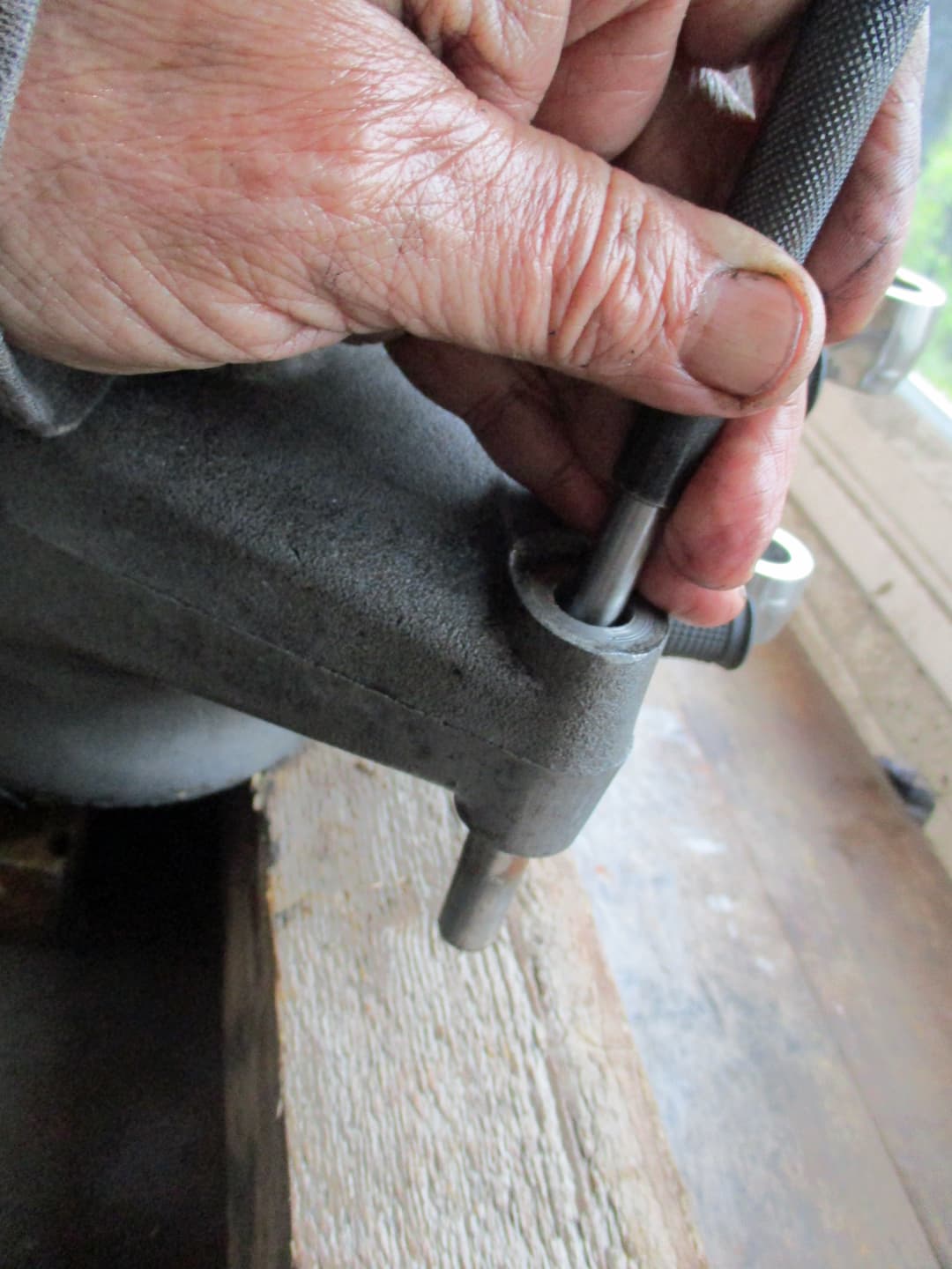
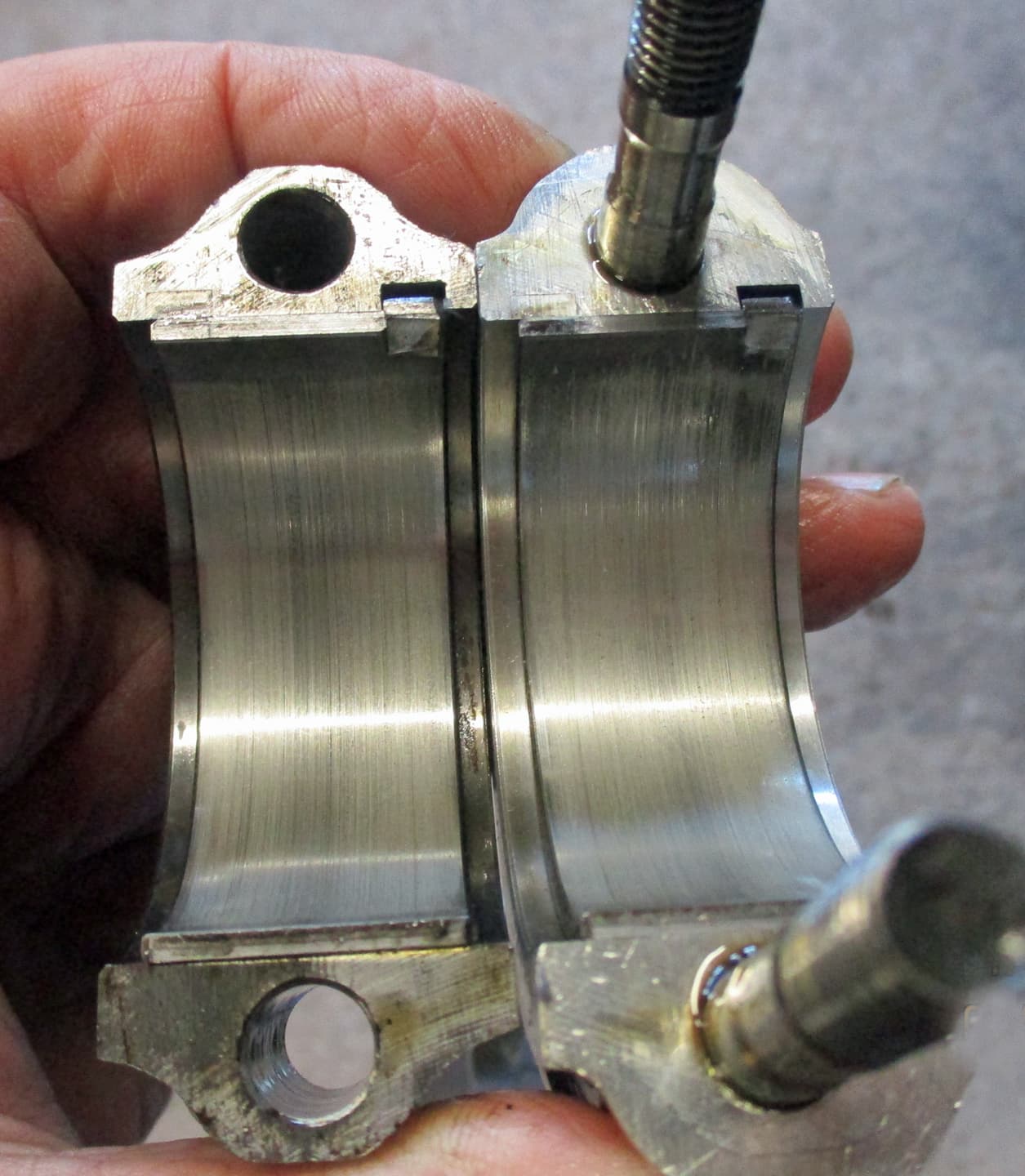
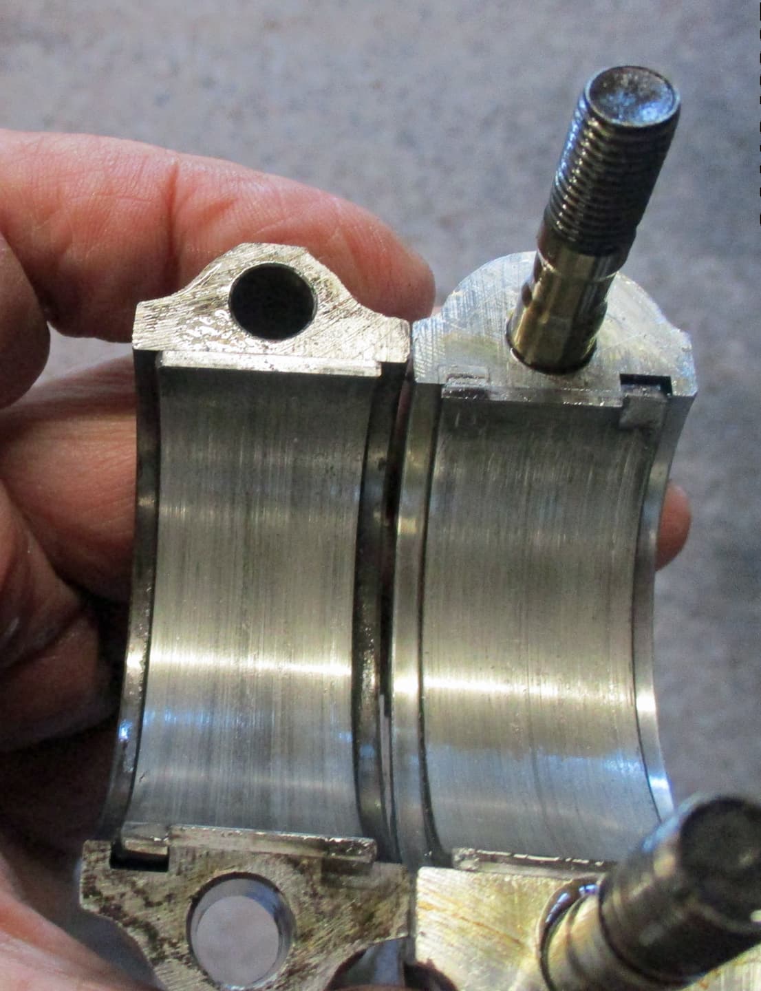
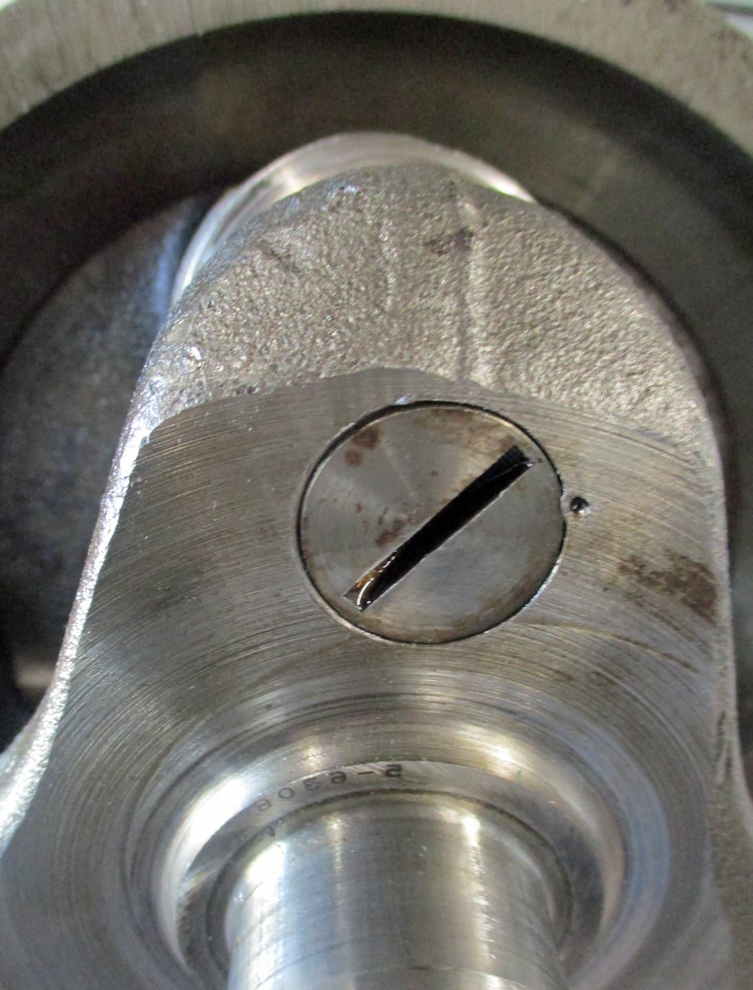
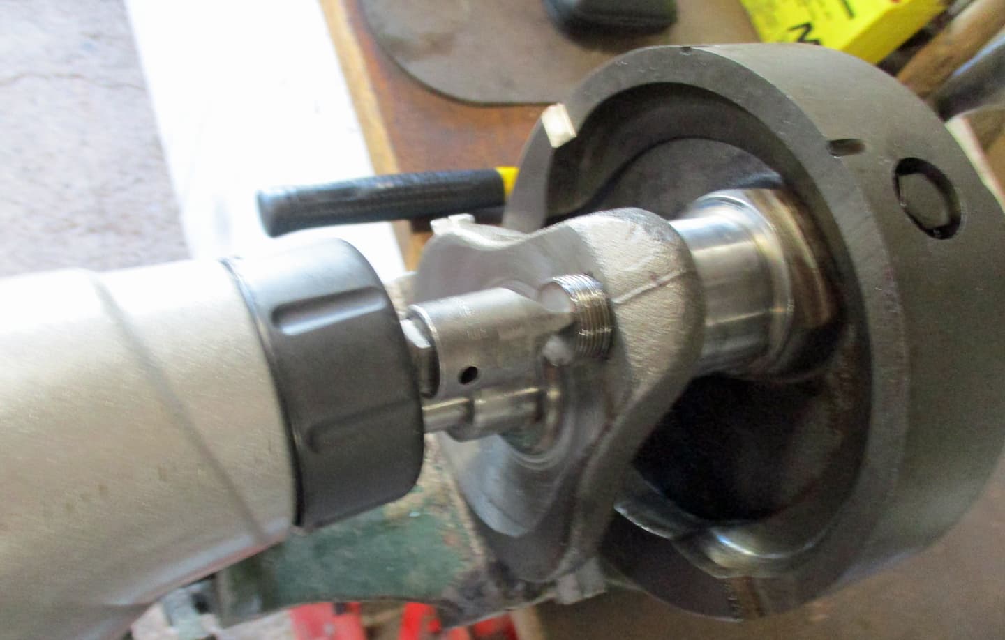
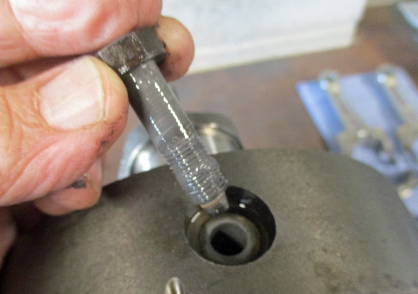
The nut in the centre of the crankcase behind the barrels can be removed to check engine timing. The crankshaft flywheel had two slots cast into it. One for Top Dead Centre and one for 38 Degrees Before Top Deap Centre.
When the nut is removed, a screwdriver - there is a proper tool that screws in but a screwdriver works just as well - can feel and hold the slots while the engine is statically timed.

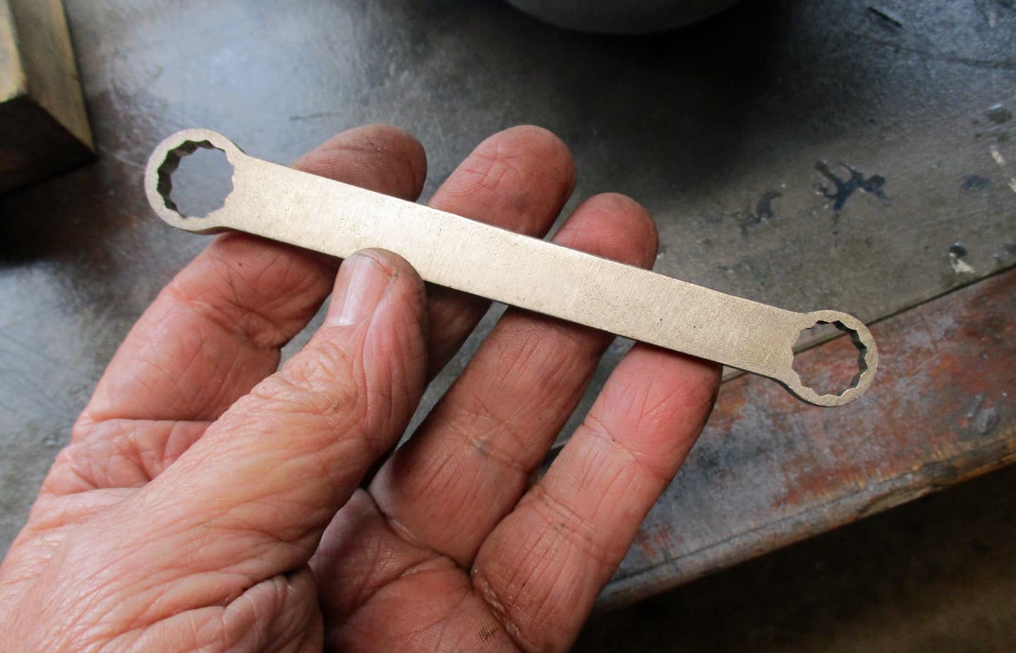
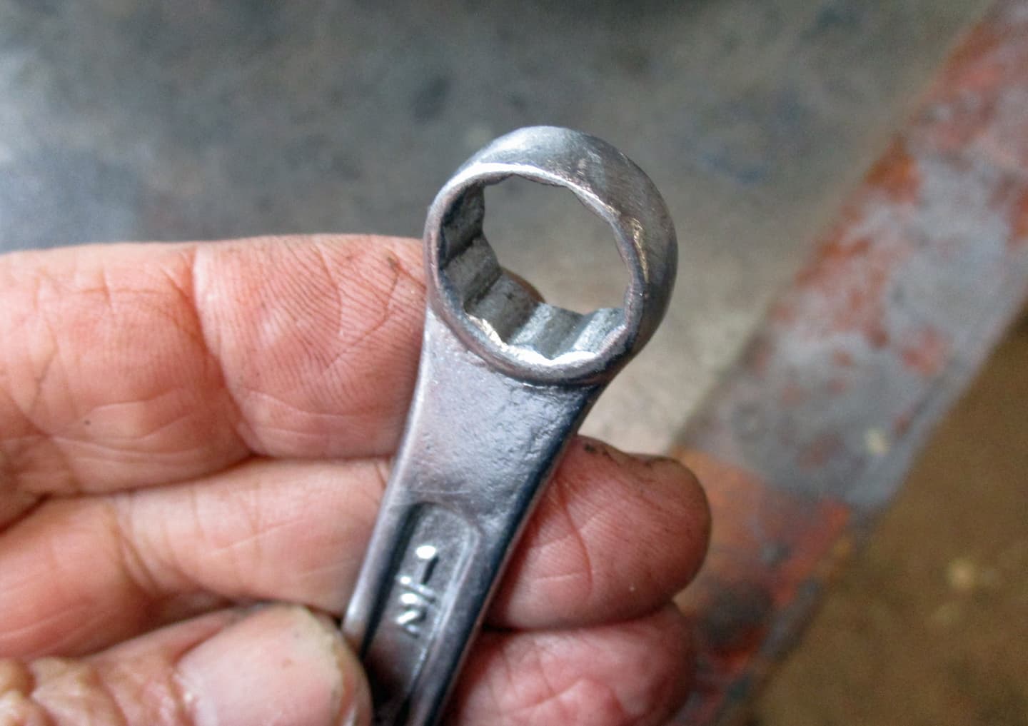
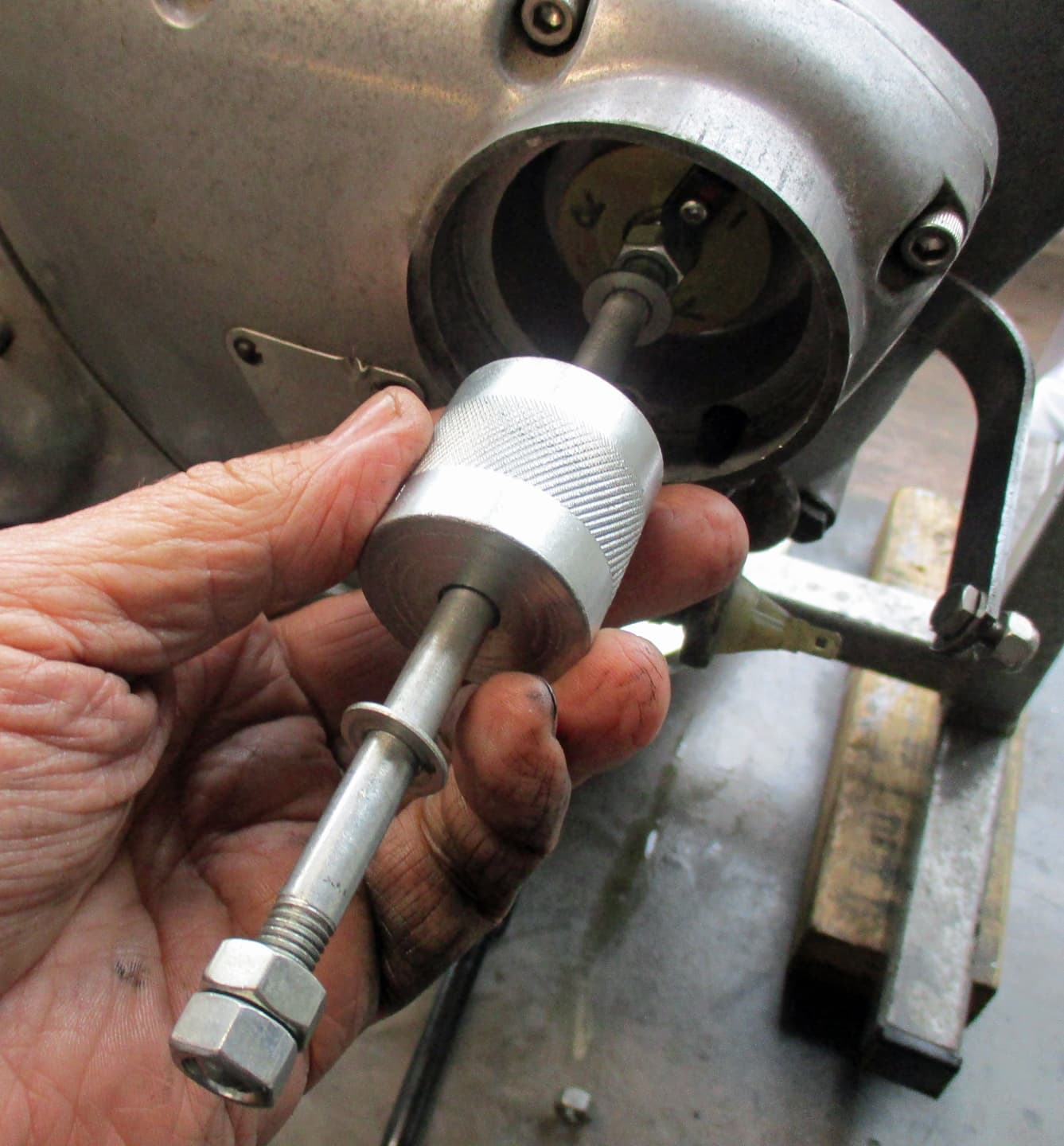
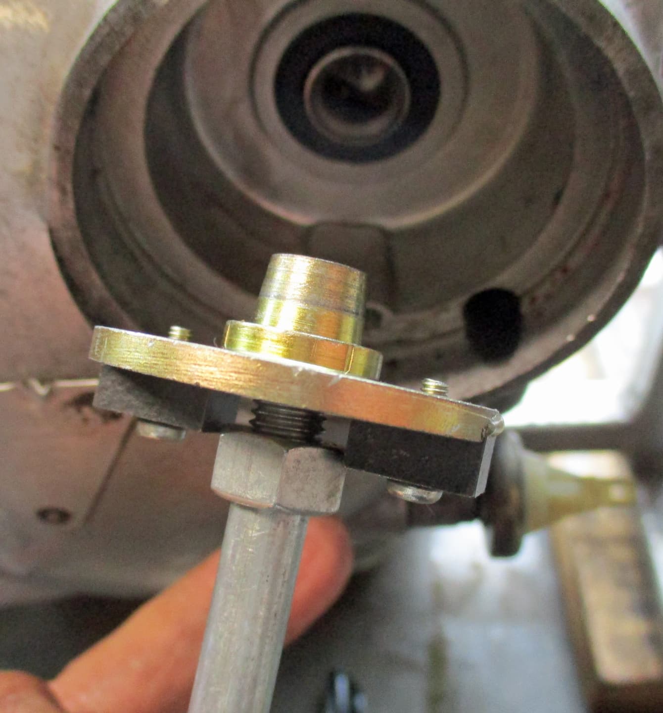
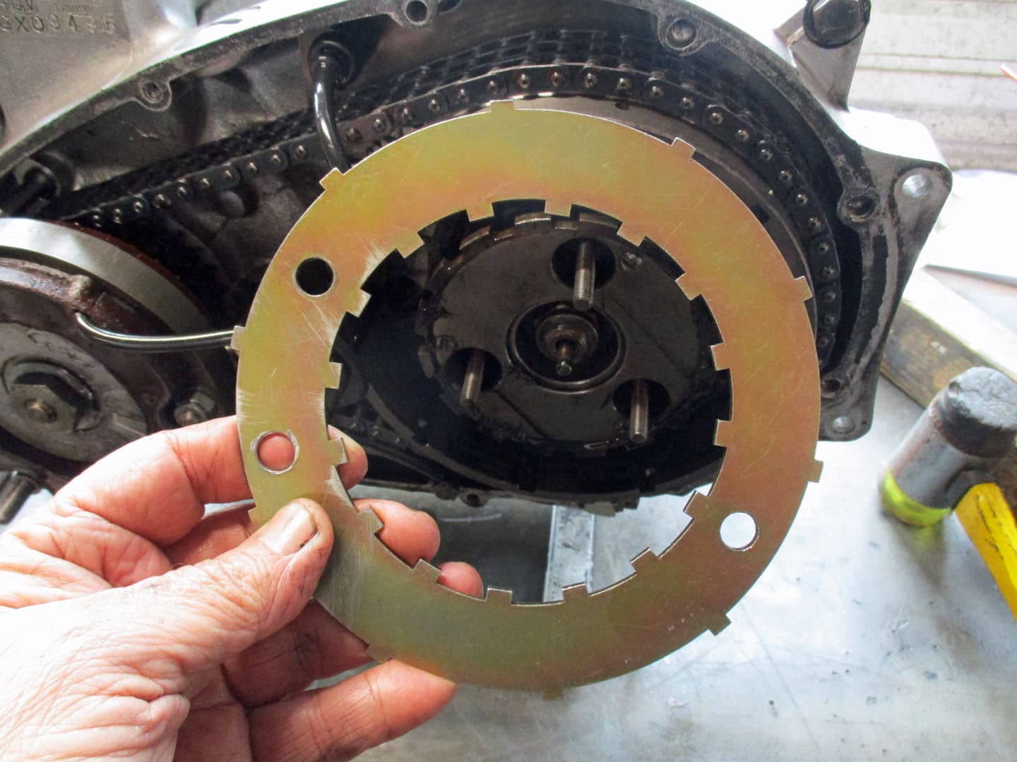
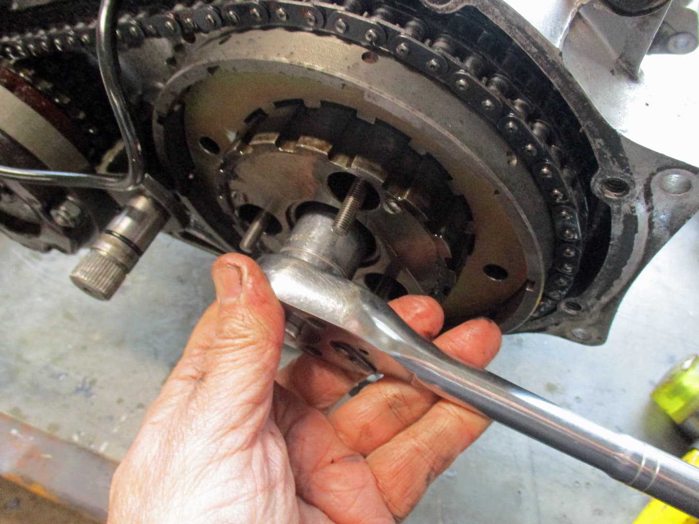
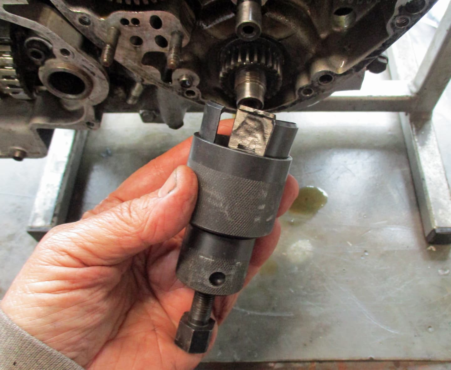
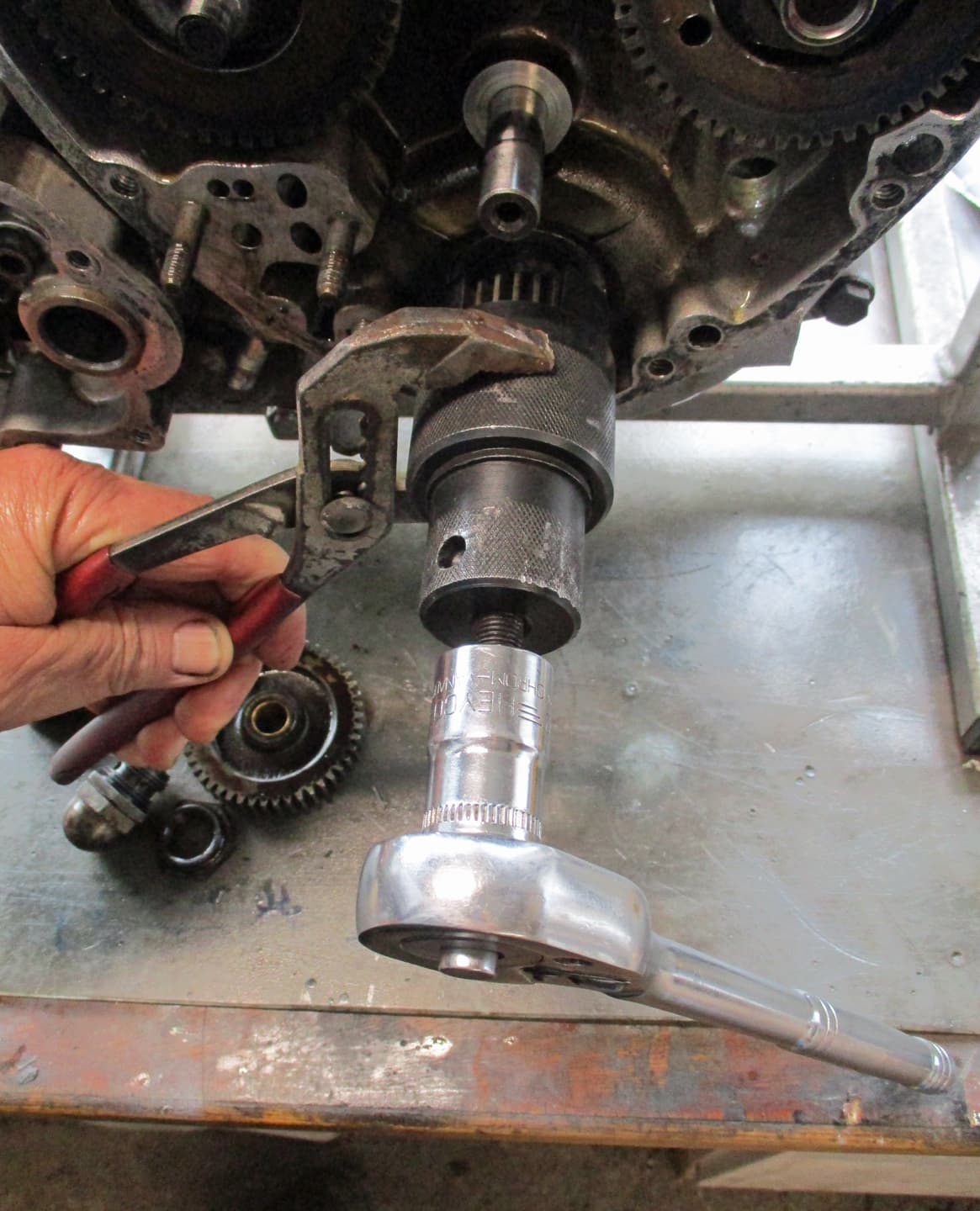
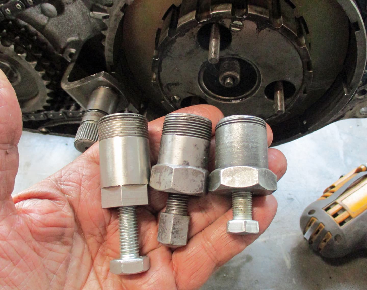
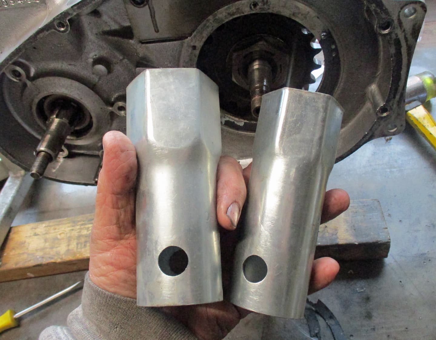
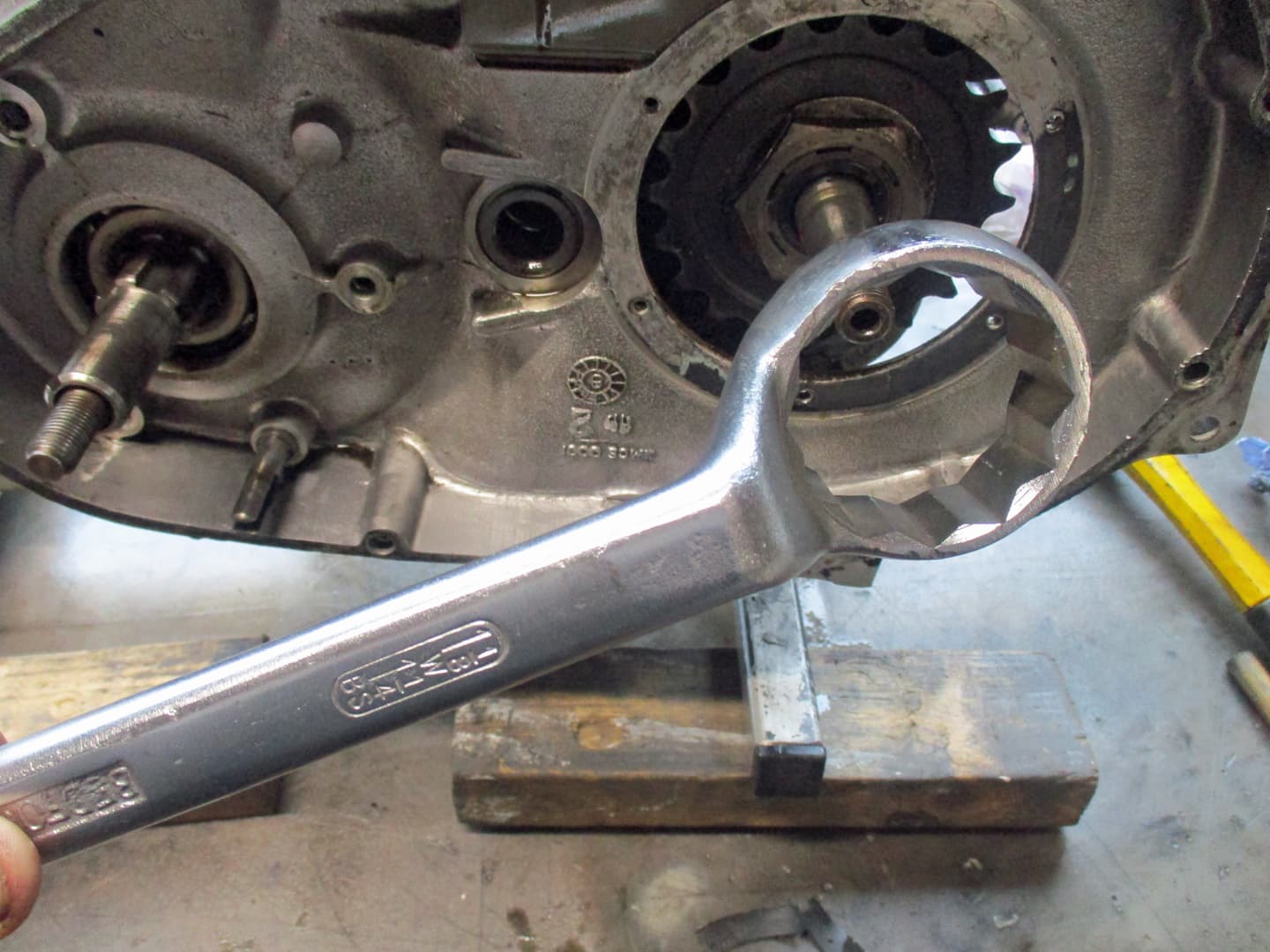
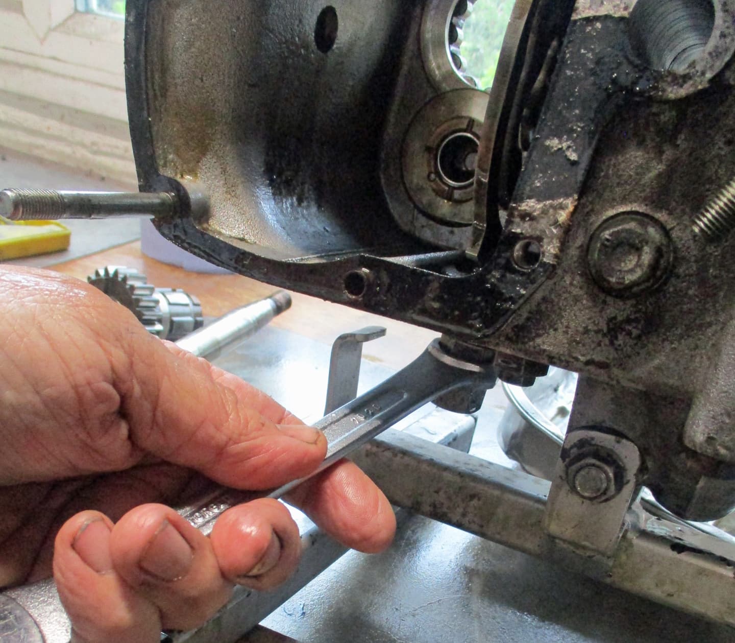
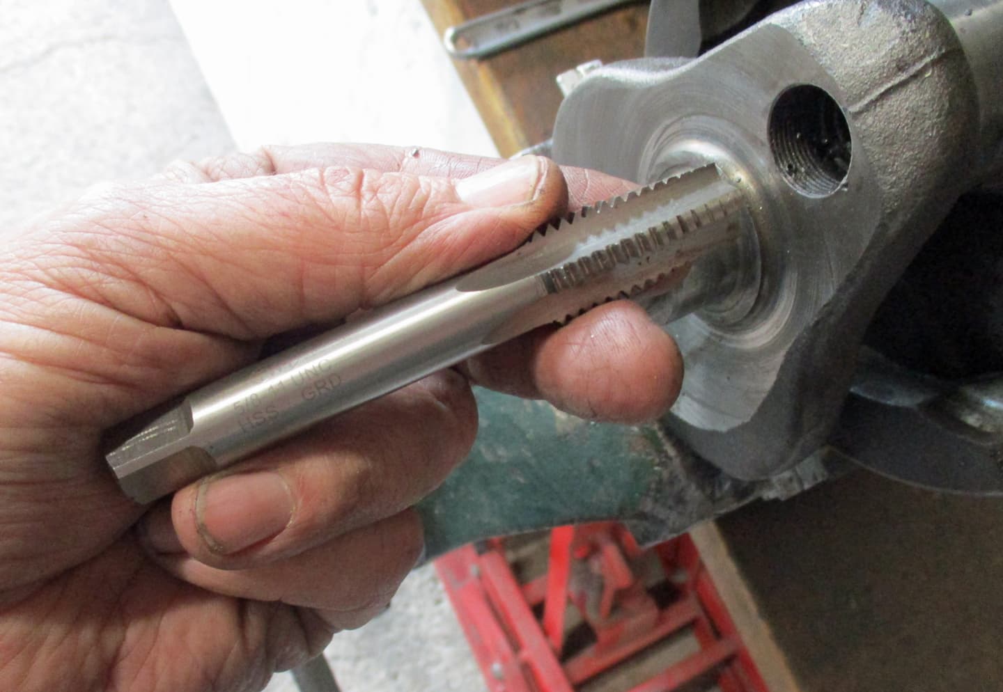
Talking of proper tools, there are a few special tools that are needed to dismantle and rebuild these engines. They are easily available and not too expensive. They can also be borrowed if you know someone who has a Triumph, but if they are in the toolbox…
Please join in with the thread, add where you can, ask and discuss. These bikes are really cheap at the moment, great fun and it’s better than watching the telly :grinning_face:
Too much talk, I’ll get on with the spanners in part two. :slightly_smiling_face: Phew…over

14 Likes

First things first is to drop the oil, all the oil…otherwise it’s a bit messy during the dismantling.

Remove the primary drain plug (earlier machines were drained from the primary chain tensioner bolt)…

…blimey! And the oil just kept coming. :neutral_face:

Triumphs prior to 1970 the primary side oil was kept separate from the engine oil. There was an oil seal between the primary side and the engine sump at the crankshaft. The crank pressures were vented through the end of the inlet cam by way of a sprung butterfly valve.

The design changed allowing the engine oil to flow into the primary by removing the oil seal and creating 3 small holes just below the crank to keep a level of oil in the primary to maintain chain, clutch etc. Crank pressures are vented through the primary.

These engines are ‘dry sump’ with a separate oil tank. Normally the oil pump would scavenge oil back to the tank leaving about 100cc in the sump and about 150 cc contained by the three hole level in the primary.

Once the primary had drained I opened the sump plug drain and removed what was in there.
There should be a total of about 250cc, that old milk container holds about 2200cc.
An annoying issue called ‘wet sumping’.

Triumphs very rarely (almost never) wet sump through just standing. Unlike Harleys, BSAs and Nortons, Triumphs have piston operated oil pumps rather than a geared oil pump.
Geared oil pumps are rubbish at holding back oil so they have a separate sprung ball bearing arrangement acting as a non return valve. The bearings don’t seat very well, the springs weaken allowing a small dribble of oil through. Over time, oil can drain down through the pump to fill the sump - wet sumping.
Triumphs use a piston pump on both delivery and return with a bearing and spring arrangement inside the pump on each side. Oil will not drain through this system unless there is a major problem in the pump. Wet sumping in a Triumph is normally due to something stuck in the pump or a restriction in the return line. Triumphs later moved to a four valve piston pump making wet sumping even less of a problem.

This is the sieve on the sump drain plug. All the oil was new and clean and no signs of any debris.

Just a remind. This is what the sieve looked like from the bottom of the oil tank - plenty of glitter in there.

Empty the gearbox of oil by removing the double bolt from under the gearbox. Again new oil taken from the gearbox.

The drain plug doubles as an oil level check. The smaller nut is removed opening the built in small pipe. When oil dribbles out the full level has been reached. Ok if just adding oil but the gearbox only takes 500cc so it’s easier just to empty and fill.

So, obviously the dealer has been in this engine even if to just change the oils. But there’s two issues already - glitter in the oil tank and wetsumping. Both will need attending to.
Both potential killers of this engine…over :face_without_mouth:

10 Likes

Onwards, in search of all that glitters is not gold…

Rocker cover off showing the plain adjuster pins and locking nuts - later mushroom types are available that don’t wear as quickly. Some one has marked I for inlet I assume.

Take the rocker box off by undoing the three nuts underneath first and then the four top bolts slowly allowing the valve springs to push it upwards. If the engine is turned over to ensure both valves are shut then they will just lift off.

Nice new gaskets, so they’ve been in here. Lift out the pushrods. These look to be coloured up on their lower half and have taken a knock about half way up.
Make a note of where the pushrods came from, best if they go back in the same place. Always have a good look at the pushrods, sometimes the ends will pull off, sometimes they are bent. Any issues then just replace with new.

Both rockers off. I’ve been impressed how clean this engine is, the PO must have pressure/steam cleaned it. certainly makes for a less messy dismantle.
I’ve numbered the head bolts. There’s 10 on a T140. Pre unit 650s were 8 bolt and unit T120s were 9 bolt. Don’t go buying the wrong head for your rebuild.

All the head bolts here are high grade steel. I’d recommend to stay with that. Stainless steel bolts have a tendancy to chemically bond themselves to the alluminium head. I’ve had one that just wouldn’t come apart, I’ve seen others online that wouldn’t budge. I tried some thread treatment stuff that didn’t work. Stick with the high grade stuff that unfortunately goes a bit rusty.

The socket nut I’m taking off here should have a washer under it. None of the sockets had washers they would tend to push into the softer alluminium head when torqued up. Not good.
In fact the normal sized washers are replaced with a larger diameter washer to help spread the load even further.
If you are rebuilding one of these and remove the head then replace the smaller standard washers with the 3/4 inch part number 82-2184 ones.

There should be a bridging washer piece under the two centre sockets. I’ve got some in the stash I think.

All bolts out and lift the head off. One pushrod tube stays on the other lifts off with the head.
There are rubber o rings at each end of the tubes, make sure they are taken out and disposed of.

Here’s the exposed pistons, barrels and copper head gasket. I don’t like the copper gaskets, even when anealed (heated to cherry red hot and cooled to soften the copper) I’ve always had problems with them. You can see where the gasket has been blowing across the centre and out towards the pushrod tube.
I don’t like to overtighten the headbolts, to try to cure headgasket leaks, as it leads to damage to the cylinder head where the sockets/bolt heads push down so I always now use the composite gaskets. The composite gaskets were developed by Triumph to try to alleviate the head gasket blowing issues at the time.

The bores look pretty good. A few scratches - maybe due to the glittery stuff getting stuck in the rings.

Head and valves look good. I’ll remove the valves to check guides etc later on.

The head bolts were in upside down. The bolts have a plain sort of nipple with no thread on the bottom that is meant to touch the bottom of the hole in the barrels. This stops any deformation to the barrels when torquing up the bolts. I’ve seen some drop a small steel ball bearing down the hole to help ensure this.

I’m really pleased with this head. There’s no damage at all to the areas under the headbolt sockets. There’s usually a significant dent caused by overtightening of the headbolts.
It’s really important on these engines to torque the head bolts correctly. Using an over strong arm when headbolts seem loose or a headgasket leak will just make matters worse.

Right, off with your barrels. First special tool is the overpriced 12 point spanner.

To reach the hard to get to, 12 point nuts.

Just grind a bit off of a half inch ring spanner and…

…it works just as well. I thought I’d break it eventually but it’s lasted for many a build.

Once all the nuts are off, the outside longer nuts are 7/16 and sometimes are a bit of a bugger to get off as they can round off easily - use a ground down 7/16 ring spanner as above.
Use a cable tie to hold the tappets into the tappet blocks (otherwise they’ll fall into the crankcases)

And lift the barrels off. A rubber hammer helps to free them but be careful not to break a fin.

And wiggle it around to pull off of the pistons. Again take your time as a broken ring will also fall into the casings. Try to hold the pistons so they don’t hit gainst the barrel bolts as damage is easy on the alluminium pistons and conrods.

I keep a handfull of gearlever rubbers to push over the bolts for protection. Some people use a rag, others a piece of pipe lag.

Prise out one of the outside piston circlips. Use a rag to block up the casings if you don’t want to be losing one down there.

Push out the gudgeon (wrist) pin from the inside (move the other piston out of the way to give access). There’s a special tool to push the pins out but I’ve never needed one, I help it out witha drift if it’s a bit tight.
Although the pins have dark staining, there’s actually no wear at all on them. Feel for grooves with a thumbnail, nothing on this one.

Both pistons off. I’ve scratched into the carbon on top of the piston which side they came from and which way is forward.
The conrods can be moved slightly side to side along the crank journal as they are designed with some float. But there is absolutely no movement up or down.
A test is to pull upwards on a conrod and tap the small end with a rubber hammer. A tick sound is a give away that the big ends are not healthy.
Each conrod should fall under it’s own weight when let go from a vertical position. One of these did not. It required a little bit of help.
Is this the first indication of a big end shell bearing problem? - that would account for the glittery stuff - but hopefully not a crank journal problem. Oh no… :neutral_face:…over

10 Likes

Brilliant, keep going…

3 Likes

Thank you, on going…
There are a few places in these engines that are torqued up and require the engine to be locked up in some way to allow the nuts to be undone - both ends of the crankshaft (timing and primary), both ends of the mainshaft (gearbox and clutch) and the big nut holding the front sprocket on.
Rather than tackle these individually - each one with a different locking method - I try to do all of them (well 4 of the 5 - sometimes the last one is actually loose already) with just the one locking method. So access is needed to all areas, which is why I take all the outer covers off first.
Here we go…

Primary cover off first. Make sure you use those labelled sandwich/freezer bags to store all the bolts in. I mostly know where bits go just by looking at them but known items in the bagging area is a good thing.

Nothing of glittery note here. I was hoping that a loose primary chain had been rubbing the casing :face_without_mouth:

There is, however, some strange dremel grinding going on. Maybe to disguise some previous loose chain marks, dunno?

On the left is the stator and rotor. The central nut is on the left end of the crankshaft.
On the right is the clutch. Behind the clutch is a central nut on the left end of the mainshaft.

So, the clutch plates have to come out to give access to the nut that needs undoing.
First undo the pressure plate nuts and springs. This is a homemade tool that allows the nuts to be unscrewed if the central bolt is higher up in the bolt. In this case the PO hasn’t tightened up the nuts onto the springs so that the clutch lever feels lighter. This clutch would have been slipping pretty quickly or worse the nuts need to be tighter to be held by the springs so they don’t vibrate off.

So, they easily inscrewed with a normal screwdriver. The nuts have a sort of nipple underneath that the springs catch onto when they are tightened correctly. Sometimes the springs will not allow the nuts to be undone so a small screwdriver is needed to push the springs off the nut underneath and can be a right git.
However, in this case they were not a right git.

The clutch plates can then be pulled out with a magnet or a couple of picks. If the engine has any age to it since the last clutch plate pull then they will mostly be stuck together or come out in two and threes.
There’s 6 plain steel and 6 friction plates all together. They have a tendancy to stick, slip or drag if the bikes aren’t used regularly. Vintage Triumph riders get used to freeing up the clutch with the kick start before trying to start the bike.
There are alternative 7 plate clutch plates that don’t stick or slip and require lighter springs but I’ll let you research that for yourselves.

The clutch centre nut is now exposed for removal.

While here just check that the rotor has a 6ish thou gap all the way round so there’s no grinding on the stator. All good here so no glitter from that quarter.

Also have a peek at the stator wiring. They have a tendancy to harden up and split where they push up against the cover. If the wiring is split then a whole new stator is required. Ok here. phew that’s a saved a penny or three but I will check for charging when, or if, I get it running.

Onto the timing cover. It’ll be needing a new Triumph patent badge.

Undo the points cover to see there’s no points but a Branston pickle electronic timing thing.

Take out the front plate by undoing the pillar bolts. Looks like someone has felt tipped notes all over this one. It’s not complicated, notes and marks are not required when installing these.

The wires were exposed and need new so I just cut them out. If the wiring is ok they’ll thread through the hole at the back of the access.
Unscrew the back plate central bolt.

And using my absolute favourite special tool, screw it into the central hole and

slide hammer it out. You don’t need this tool, a long bolt will do the same thing. The plate is only held in on a taper and is easily knocked out. But I like this tool - I’ve been known to put the plate back in so I can get it out again :smile:

Take out the oil light switch. A note - these are on a tapered thread. Ok to take out but be careful putting them back in - over tightening may crack the cover.

Unbolt the timing cover. Put those bolts in a labelled freezer bag and note where the 2 long ones go.
The central intermediate wheel gear isn’t bolted in. It can slip out if the shaft is stuck in the cover. The engine will need to be retimed if this comes out. Not an issue as it’s easy to retime just be aware.

Inside the timing cover. Looks complicated but it’s not.
The bottom smaller diameter pinion is bolted on and driven by the crankshaft.
This then drives the cental intermediate wheel…
which then drives the top two cam shaft pinions. These are on the end of the two cam shafts that have timing lobes to drive the pushrods up to open the valves when required.
The right hand cam shaft also drives the rev counter drive on the other side of the engine.
The left hand cam also drives the brass oil pump seen here on the left side. The cam has an offset pin that moves in a crlcle driving the pump’s pistons up and down.

Moving to the left take off the outer gearbox cover. Again a mixture of bolts and nuts here so label and bag them up. Expect more gearbox oil here as it will not have all drained.
The kick start spring is inside this cover and is wound up. When the cover is released the kickstart drive will unwind quite agressively. I always, therefore, take off the kickstart lever so it doesn’t twat me in the ear. When the cover is off by about a half an inch I release the spring with a screwdriver from the stop.
You can, just hold the kickstart in place so it doesn’t fly round but an extra hand is needed.

Inside this cover is the clutch operating mechanism. The clutch cable pulls on this clover leaf shaped cover. Under the sprung cover are three ball bearings.

When the cable is pulled the cover rotates lifting it up on the bearings. This pushes on the clutch pushrod that in turn pushes on the clutch pressure plate. It doesn’t move much but it’s enough to pull the clutch plates apart stopping the drive to the back wheel.

The mainshaft nut on the gearbox side and the crankshaft nut on the timing side are now exposed for removal. Goody gum drops…

7 Likes

Right, a quick long note, it seems an appropriate time - oil.
The lifeblood of the Machine God. Here’s an almost good diagram of the oilways in an Oil-In-Frame 70s Triumph:

Tricky to get your head round but a basic understanding is required to know what’s going on in the timing cover just removed.

The oil is drawn in from the feed pipe by the rising feed piston in the oil pump. The valve shuts in the pump and when the piston is pushed down it forces oil out of the left hand hole in the crank casing. The oil is forced into the left hand oilway in the timing cover.
The oil travels through the pipeway in the timing cover to the central hole and is forced through the oil seal into the centre oilway in the crankshaft. This oil then travels through the sludge trap and into the big end bearings, then drains down to the sump and then back to the frame tank.
The oil can carry on in the timing cover to enter the right side hole oilway to the pressure relief valve. The pressure relief valve is a piston on a spring that will move if the oil pressure is high enough. If the piston moves then the oil by passes the pressure relief valve and is dumped into the sump. The oil pressure then falls to safe levels (ie it doesn’t blow all the oil seals and gaskets) the piston in the pressure relief valve gets pushed back by the spring and oil is again pushed through the crankshaft.
It is really important that the correct pressure is maintained to keep oil flowing to the big ends. If the pressure relief valve fails or the oil seal in the centre bottom of the timing cover fails (or turns inside out) most of the oil will end up in the sump only some or no oil will get through to the big ends.
If the sludge trap blocks due to not being cleaned this will also stop oil flow to the big ends and generate enough pressure to open the pressure relief valve to again dump oil into the sump.
Wet sumping will obviously occur in these conditions. The loss of oil pressure will cause the oil light to come on. Do not carry on to the next junction, stop and investigate.
The engine will seize and throw a big end through the casing very quickly without oil.
Just so you know :slightly_smiling_face:…over

9 Likes

I sincerely hope the people at Haynes are quaking in their boots.

4 Likes

I agree. This is seriously the best, clearest and most knowledgeable explanation of an engine rebuild that I have seen. I don’t myself have any plans to rebuild a classic Triumph twin (I probably won’t buy another classic bike as I have two already, and, if I ever do, it will be a Velocette single), but @Iron’s explanation would certainly tempt me to tackle the job if I had a T140. .

4 Likes

Thanks Chaps…
Now to lock the crank and clutch up to enable the further delving into the engine

An extra timing pinion is used to lock up the crank. They are easy to get hold of, just get the cost out of the special tools fund. You need a special tools fund.

Put the extra pinion gear in here. It’ll lock the timing gears up.

The nut on the crankshaft holding in the pinion gear is the first to get off.

All the nuts are normal right hand thread. They are not over torqued and should come off fairly easily. I just loosen this one off for now as there’s a bit more to do to get the pinion off.

Move across to the other end of the crankshaft and flatten off the tab washer on the outside of the rotor. Don’t get too carried away here as I hear that hitting the rotor can cause it to loose some magnetism - it may just be bullshit but I don’t know so just weenie taps here.

And loosen the nut. Again not over torqued so easy to sort.

Move to the clutch which now has no clutch plates in it. It also needs to be locked up. Another special tool here that is a plain plate and a friction plate all in one. It has the tabs that fit into the slots in the basket and also the clutch centre.
If you dont have one of these you can drill a couple of holes through a friction plate and a plain plate and bolt them together.

This is the centre nut on the end of the main shaft that has to come off. Sometimes there is a tab washer rather than a locking nut. So have a peep up the hole just to make sure which one you have, this is the later locking nut so no tab washer to mess with.

Loosen that off.

Move across to the other end of the mainshaft in the gearbox cover. Bend flat the tab washer there. As with all the tab washers, I’ll be replacing with new as they crack easily when over used.

And undo that nut.

Removing the nut here will allow the kickstarting non return mechanism to come free.

This is the order it comes off in. Make a note of which way round the last washer comes off and keep all safely in your labelled freezer bag.

Back to the timing side and take the two dished nuts and serated washers off of the oil pump.

Pull the oil pump off. I’ll be taking that apart to inspect and discuss that later on. Have a look at the pump’s gasket against the casing. Make sure it hasn’t been restricting any of the oil flow by being positioned in correctly (some can be put on the wrong way round) or are just not cut correctly.

Pump gasket removed and in the bin. Note how the holes are different. they must not be obscured in any way by the new gasket.

Remove the oil block and it’s gasket. Make sure all the pipework is clear and clean.

Back to the timing side. Remove the intermediate gear wheel - it just slides off, it may bring the spindle with it, that’s ok it just slips back into the hole.

With the intermediate gear out the cam shafts are free to spin.
Hold the cam gear on the inlet side and give it a pull and a push to check there is some end float. Then put your hand into the casing and rotate the cam. Feel if there is any movement up or down of the cam within it’s bushes. I’ve only ever had one of these needing new bushes installed. They hardly ever need work other than cam replacement. This one is fine so no need to take the camshaft out.

Same feeling around on the exhaust cam. End float ok and no up or down movement in it’s bushes. That can stay in as well.
The crank cases can be seperated with both cam shafts in place so leave them be unless there’s a problem. They are a bit of a bugger to reinstall so leave them if you can.

Onto the removal of the pinion gear. Take the already loosened nut off noting whic way round it goes.

And while here take off the Pressure Relief Valve as well. Take it off as a whole unit, don’t unscrew the domed bit yet, get the spanner/socket onto the bottom hex.

Note the sieve on the PRV. It has a fairly fine weave. On the 3 cylinder Tridents and Rocket 3s the weave is wider because I think they need to drink more.

Now this is a special special tool. Basocally a three jawed chuck that grips over the back of the pinion gear to pull it off. If you look closely you can see where I’ve had it apart to grind some metal out of the fingers so it gets a better grip round the pinion.

It gets pushed over the pinion and tightened up to grip behind it. As the engine is no longer locked up the tool has to be held with some grips while the bolt is tightened to pull the pinion off.

The pinion isn’t on a taper so it pulls off fairly easily.

Here’s the removed pinion gear. You can see the timing mark above the inner key slot. The timing mark will be used later when timing the engine. The nut holding the pinion gear in has a habit of covering this mark up when tightened up. So some make another popmark or add a bit of paint so the timing can be more easily seen.

Take out the woodruff key. Use some side cutters if it’s hard to get out. Look for any damage make good or renew if necessary.

Take out the clamping washer noting which way round it fits. You may need a pick or magnet to get this off once the woodruff key is out.

Over to the other end of the crankshaft. Remove the shouldered nut and tab washer.

Undo the nuts on the 3 stator bolts and wiggle waggle the stator off. This is normally a right bollox to get off due to the rotor magnet pulling it skew and getting caught up on the flat strips of metal. It will come just adopt a wiggle waggle method and some interesting swearing.

Pull the rotor off and the square section key.

Slip off the large thick spacer.

Move across to the clutch centre and take out the loosened centre nut and the thick washer.

Another special tool here. I seem to have a selection here as some are better made than others.

Wind the centre bolt of the removal tool out to give plenty of room while inserting into the clutch centre. There is an internal thread in the centre of the clutch that the removal tool screws into. get as much thread screwed in as possible as the clutch centre will need to be pulled off of a taper joint.
Hold the tool with a large adjustable spanner while winding in the central bolt. It’s takes quite a bit of force to pull the clutch centre off of the taper.
It will make a loud bang - like something has snapped - when it releases.
And breathe…

All of the nuts etc came off pretty easily on this engine. Sometimes any or all of them can put up quite a fight. Sometimes a bit/lot of fire helps, sometimes heavier methods can be adopted and sometimes cutting/drilling the offending part is required.
The usual issues are normally caused by POs using copious amounts of blue or even red locktight - that break down with the application of copious amounts of heat or an additional method of whacking it with a bigger hammer.

Now that all the nuts are off the primary side chain and sprockets acn be pulled off. This is a continous chain so the front sprocket and the clutch has to come off (and go back on - which can be entertaining) as a unit.
Sometimes the front sprocket can be stiff to get off. It has two threaded holes in it that can take a puller. The headbolts already removed have the correct thread so thay can be used in a puller if required.
The gear change spindle (adopted to transfer the foot change from the right side to the left) has to be pulled as the clutch basket comes off, it slips out easily.
Occasionally the clutch centre will pull out of the clutch basket dropping all the clutch roller bearings all over the place. Don’t worry, nothing has broken. your work has just been made a bit easier, collect all the rollers up (there’s 20 of them) and pull the clutch off in bits.

All off.

Behind the front sprocket is a spacer to remove and store.

It may not just be one spacer, they may be a few very thin ones as well. Only one in this case.
These are required to ensure the teeth on the front sprocket align perfectly with the teeth on the clutch basket. This allows the primary chain to run straight and reduce wear.
I’ll go through the alignment process on the rebuild. It’s pretty simple.

Take out the woodruff key from the mainshaft behind the clutch. Sometimes they are difficult to get out so side cutters will grip and get them out. Make sure any damage is filed out of the key or it’ll be a bugger to get back in on the rebuild.

Woodruff key with the round bottom. Which can make it swivel in it’s groove when putting the primary chain and clutch back on - it may be called rude names later.

Slide out the gear change spindle. A bit of surface rust but it will polish off easily.

Primary/clutch assembly for inspection. Stand by your beds…

7 Likes

I’ll be digging into the removed rocker boxes, primary/clutch and barrels/pistons later on. Carrying on delving deeper into the engine…

The stator is still wired through the little hole in the casing, so cut the bullet connectors off

and remove stator, including the rubber plugs that stop oil from escaping the primary.

Remove the cover from the rev counter drive

The worm gear slides out using a magnet.

Then undo the connecting piece with some needle nose pliers. It can be either right but mostly left hand thread.

And take off the drive. A threaded plug can be purchased if leaving the drive off but I’m planning on reusing this one.

Unbolt the exhaust brackets.

Take out the primary chain adjuster bolt. This is an area where owners get a bit frustrated with an oil leak and can overtighten or ruin the thread in the casing. Check for cracks around the hole. There are no easy fixes for damage here.

Unscrew the tension on the adjuster with a flat bladed screwdriver. An almost impossible task with the engine in the frame. There are special bolts with a blade at one end but an appropriate little tool can be made up easily for when the engine is back in the frame.
The whole design for the primary chain tension adjustment was awful. They tried to make it a bit easier on models after 1979 but they just leaked more oil. Just a bad design that can be an arse sometimes.

Pull/slide off the tension blade from the abutment. Replace the blade if it’s worn down.

The circular cover behind the clutch has to be removed to gain access to the front drive chain sprocket.

These flat head screws can be a bit of a git to get out. Sometimes reverting to a manual impact driver to free them. Screwdrivers that can take a spanner are useful especially with oily hands.

The cover won’t come off easily. Use a wooden drift around the back between the sprocket and the casing to break the joint. Then pull the cover off from the inside.

Cover off and access to the front drive chain sprocket. The sprocket is held on with a large diameter nut. Sometimes these are only finger tight or actually loose from no maintenance.
In this case it was tight.

So, to undo, a large diameter socket is required and the sprocket needs to be locked up.
An old chain can be threaded back onto the sprocket and held in a vice or there are special little lengths of chain with a bar that can be inserted to hold the sprocket.
I had a bit of an accident when the socket slipped trying to undo one of these a while back (claret, stitches, etc) so I don’t use those methods anymore.

I bought one of these. A proper bigboys ring spanner.

Knock flat the tab washer.

Put the ring spanner onto the nut and turn it so it’s held from moving by the end of the crankshaft. Then use a drift and hammer to turn the sprocket to undo the nut.

Easy, no pain. Take off the nut.

And the tab washer. Note how it slots into the drive from the gearbox.

Due to oil seeping along the splines from the gearbox an oil ring was added. Use a pick to remove.

And fiddle the sprocket out. Sometimes clever clogg owners installed larger diameter sprockets and the casing will have been filed to allow the sprocket teeth through the casing.
My advice would be to go back to standard. We’re not racing around cafes any more.
Not quite there yet, gearbox out next…over

8 Likes

The gearbox is something that worries a few people. They are pretty simple animals if time is taken to take them apart and keep a record of how they come apart.
It helps if there’s understanding of how gearboxes work but it’s really not essential. Plenty of diagrams in workshop manuals etc.
The only bit that sometimes requires a walk round the garden is indexing the bloody things once they are back in.

Take off the gearbox inner cover. There’s 3 different bolts. This one is an allen bolt.

Then the phillips head type bolt. Sometimes the crosshead is a bit monged and a manual impact driver is needed. Replacement bolts and even allen headed bolts are easily available from dealers.

And a normal hex headed bolt that is sometimes forgotten as it’s not actually inside the cover.

Remove the inner cover. It normally needs a bit of persuasion with a rubber mallet. The gear operating quadrant will fall out of the gears on the back of the camplate as the cover is removed. Not an issue it’s meant to do that. It stays in it’s place, it’s just swinging around.

Once the inner cover is off check for the brass thrust washer that may be stuck on the inside, or it may still be on the layshaft. Keep it safe.

Inside the gearbox remove the dog gear from the layshaft.

Then with some appropriate pliers take off the circlip retaining the gears on the layshaft. For the cost I always replace these as you really don’t want it to come loose under load. They can get bent fairly easily and lose their ‘grip’.

The rest of the contents of the gearbox can then be drawn out piece by piece. Thread the gears back onto their appropriate shafts as they are removed. Again, no real need to do this as they are pretty simple to ‘rebuild’ if you have a manual with a picture of the gears in.
If you haven’t got a picture here’s one. Pay attention to how the selectors are positioned

Pull out the high gear from the main bearing and thread it back onto the mainshaft

There’s another brass thrust washer around the layshaft bearing. Take it out (it’ll only fall out when playing with the cases and it’ll be lost) note how it has a hole to fit over the little nipple.

There’s a detent holding the camplate in the floor of the gearbox. Each ‘slot’ in the camplate that is retained by the detent as the camplate moves round is a gear. Here it is in neutral, the ‘slot’ to the right is first etc.

Unbolt the detent from underneath.

The detent is actually a point on a spring in a tube. It can be pulled apart to check it. Improved detents are available that have a ball bearing in place of the pointy bit. I have one in another T140 and I don’t think it makes any difference.

The cam plate pulls out of it’s retaining hole. That’s the gearbox out. Store it as a unit (put together as best you can) in a plastic box and spray it with oil. No rust required here.
Again I’ll have a look at condition etc later on.

The plastic breather connector can be removed from the top of the casing. Alluminium alloy ones are available if the plastic is brittle or broken.

That’s it. All ready to get the casings apart.

Note - although it’s taken me 3/4 days of photo editing and one fingered typing to get all of this in here. It’s really not even one day’s work to get one of these engines apart. The work can be held up on occasion by stubborn nuts, bolts and parts (such as stuck heads, clutches and casings) but with a bit of ingenuity, some fire and a large hammer they usually do as they are told.

9 Likes

Onwards, on the quest to find the stuff that glitters

Undo the 3 crankcase bolts on the top left side of the engine. Make a note of which one came from where as they are different lengths.

Take the egine out of the stand and undo the front/bottom through bolts and the two larger diameter b long bolt and nut from the middle section. Sometimes the nut will bring the long stud with it. not a problem let it come.

The front engine mount has a hollow dowel (T120 engines do not have these) that needs to come out.

It easily hammers out with a drift.

Now the casings are free to come apart. Sometimes these are easy, sometimes they are a bit of a bugger. There is a puller that will help get them apart but I haven’t needed one as yet. (Good job 'cause I haven’t got one). This one has moved apart by about half an inch.

A bit more pulling and teasing and it’s apart. Hooray.

This is the primary side casing. You can see the main crank bearing and the three little holes that maintain the oil level in the primary case.
This main crank bearing is actually in two parts. The centre race and roller bearings can pull out from the outside race. Normally the inner race will stay on the crankshaft as the casing is pulled.

The other side of the casing doesn’t normally just pull away from the crankshaft it is usually a normal ball race bearing. It is tempting the hit the crankshaft end to force it out of the centre race. Not only does this not work it will actually distort the end of the crankshaft.
It is this end of the crankshaft that sits inside that oil seal in the timing cover to ensure oil gets pushed up the crankshaft.
So the trick is to set up some wooden blocks - or as in this case a couple of stools - and drop the crankcase about one inch onto the blocks. The crank will them fall out of the bearing/casing. Obviously the stools I am using are a bit high but I catch the crankshaft as it releases and place it down on the bench.
I noticed a piece of metal on the bench when the casing and crank was just held there. It is arrowed. I picked it up and though it was the round end broken off of a split pin - maybe something I’d done before. Yeah right.

Here’s what I found in the other half of the casing once the crankshaft was out. I’m pretty sure it’s the glitter that isn’t gold. Blimey…

Sure enough glitter from the corners of the crankcase.

And the separated cage etc. from the bearing. The wearing on the outer side of the cage is from where it was loose and hitting the crank. You can see why I thought the piece that fell onto the bench was an end of a split pin.
If you look at the lower dips in the cage you can see where these bearings are spot welded together when they are manufactured.
Apparently, even small amounts of rust can cause these, and even the roller bearings to become damaged in this way when under load.
Any bike with a crankcase or gearbox or cavity of any type can suffer from condensation. A warm bike in a cold garage, a warm day that cools overnight etc etc.
If the bike is left for a length of time then the water can form rust on exposed steel. A short exposure wouldn’t be too much of a problem but left for a long period may cause an issue as above. Remember the rust on the gearchange rod?
I try to ensure all my bikes get turned over with the kickstart fairly regularly during the winter, easy to do even without a battery.

Here’s some small bits of info from the great John Healy of Coventry Spares:

john healy 1

Engine completely apart. Sludge trap and big ends here we come…over

7 Likes

Driven by poverty, I put a second hand gear cluster into a Venom gearbox in my distant yoof, when I knew even less than I do now. It worked fine afterwards, so it can’t have been too difficult…

3 Likes

Nearly there

Crank in the vice

Label up the conrods so they go back onto the correct side and the right way round.

Undo the big end nuts. The conrods will already have a punch mark to ensure they go back together the same way.

Primary side rod labelled.

And again, the rod is already marked - sometimes there’s two punch marks

Both rods off. The bolts will need to come out to be measured to ensure they are still in spec. or for renew.

The shell bearings don’t look too bad. Renewing anyway as they are a cheap replacement. The crank journals will need to be measured to ensure the correct size.
The crank may have already had a grind in the past. The journals can have up to 20 thou taken off which will require thicker shell bearings.

This is the dreaded sludge trap with it’s screwed in plug. This plug looks original and looks to never taken out due to the single punch mark. It is traditional to add a punch every time the plug has been out.
There’s lots of info out there on how to remove these. I’ve had to drill them out in the past.
This one should be fine if it’s original, no locktight (that’s what the punch is for - to keep it from unwinding), proper steel, correct size, not threaded…

I made up a special rounded off link bit to fit the slot exactly.

Hammer the bit into the slot…

…and get the big guns out. This is a mains powered impact, not battery, no extra extensions or links just full on heavy duty arm breaker.

Brrrrrrrrd, straight out, no need to drill the punch out, nothing, straight out no bother.

Here’s the plug. Correct thickness so it doesn’t cover the oilway. So good it could be used again but I’ll replace with an allen key type. Give the next puller a hope of getting it out without heavy tools.

Doesn’t look too blocked up in there. But it needs a clean and the tube will need to be pulled out.

First take out the retaining bolt that holds in the tube. The tubes are notoriously difficult to remove. Again, lots of advice out there.

My method is to thread the tube with a 5/8 tap.

It’ll centre itself and only tap the tube as it’s narrower that the hole in the crank. The plug has a 7/8 thread.

You can see the threaded section in the tube.

Using a 5/8 threaded bar with two nuts

Double nut the bar into the tube, then using one of the nuts against the crank pull the tube out.

No problem

Order a new tube as this one is a bit mucky and squashed up being in the vice to get the threaded bar back out.

And that, my friends, is that. Grassy Arse :slightly_smiling_face:

14 Likes