You are a Genius
2 Likes
You’ve missed a bit… ![]()
![]()
Seriously though, wow.
Thanks gang. It took me ten times longer to write about it than to do it and a lot more boring too. But at least it’s here now.
@ducatitotriumph I’m going to have to have you shot now. I’m sure you understand, ![]()
1 Like
If you wouldn’t mind using a ducati gun, I’m sure it’ll be out of warranty, miss fire and then fall to bits!!??!! ![]()
Abso 'kin lootly amazing!!
You have more than one gift - doing it AND telling it to perfection and with apparent ease!
Thank you @Iron for the masterclass. You and darkman are forces of nature at work and it’s awesome (literally) to watch/see!
4 Likes
Although I have no intention of ever rebuilding a classic Triumph twin myself (if I ever buy another classic it will be a Velocette single, and I did once rebuild a Venom gearbox), I have been deeply impressed by your knowledge, @Iron, your ability to explain what you are doing and by the clarity of your photos. Well done, sir.
3 Likes
The other way to get the washers in the coils is to firmly grip the hook at one end of the spring in the vice and then bend the spring one way, insert the washer, bend it the other way and do likewise on the other side.
One other method I have seen used is to hook the spring over its top peg and tie a stout length of cord to the bottom of the spring. The other end of the cord needs to be tied around the rim and tyre of the back wheel. By moving the bike forwards the spring will be stretched sufficiently to be able to engage it on the stand.
3 Likes
A couple of bits came today so allowed me to do a few jobs

Changed that layshaft circlip for a new one

Just put the inner and outer gearbox covers on temporarily. The inner cover above has to be indexed correctly when permanently fixing but I’ll show how that’s done when we get there.
I’ve actually seen a couple of bikes for sale because the owners couldn’t index the gearbox. It can be proper frustrating requiring a quiet walk around the nearest field while contemplating the clouds.
Fun fun fun ![]()

I always change the inner cover screw headed bolt for an allen key type. The screw heads can be a real issue to remove if tyey get chewed up with an overaggresive wrongly sized phillips screwdriver.

Drilled a hole in the battery tray and bolted on a new weenie brake fluid reservoir - this one has the exit pointing in the correct direction.

Made a stainless tank tie strap. these don’t hold the tank on, they stop the tank twisting and also keep cables and the like in place.

Then back to the primary side of the engine to fit the front sprocket.

Nice new 20 tooth sprocket. grease the race that will turn inside the oil seal to help it into place.

The sprocket is an exact fit into the splines and, sometimes, can be really difficult to get on. They all slip on easily once thay are offered up dead straight.
A tap with a length of wood is sometimes required to get the teeth through the opening in the primary case and seated into the oil seal.

Make sure the sprocket is on all the way. It needs to go passed the groove for the ‘o’ ring.

I then apply some sealer as oil can make it’s way along the splines. I’ve carried this habit on to T140 engines from T120 builds as a sort of belt and braces. It’s probably not required as there’s now an ‘o’ ring.

Make sure the ‘o’ ring is pressed fiemly into the groove on the splines of the high gear. It doesn’t want to go in by itself, press it in with a fingernail or with the head of a nail if you bite yours.

Then the tab washer. The spline tabs point outwards away from the engine.

And then the nut. The flat side in towards the engine. Sometimes these go on easy sometimes they are a bit of a fiddle to get started on the thread. It’s a normal right handed thread.

The nut is done up with the large box spanner. There’s one for a T120 and a slightly bigger one for the T140.
These spanners slip easily off the nut - as I’ve found out having several stitches put into the web between my 2nd and 3rd fingers of my left hand a couple of engines ago. So be bloody careful as it hurts a lot getting the injections into the cut so it can be stitched up.

Normally, I would be building the engine on the bench so I’d stick an old chain onto the sprocket and clamp it into the vice to stop it turning so I can tiughten up the nut.
So a new method was required.
Throw on an old chain and stick a bar (in this case a large screwdriver) through a hole in the back sprocket and into a hole in the back disc brake. As the sprocket wants to turn backwards when tightening the bar is stopped by the swingarm.

Tighten the sprocket nut up. Enough so that if it slips off you’d hurt your hand. Make sure the slippage area doesn’t have any protuding bolts to rip into your knuckles.

Bend the tab washer over to keep the nut where you want it. I discover quite a few of these are loose when embarking on a rebuild - probably because no large box spanners were available - so a hammer and a screwdriver were used to try and tighten the nut.

With an old chain on it gave me a chance to look at the engine/wheel alignment. Looks pretty good.

A new tank fixing bolt kit arrived (the old one was well rusty and I couldn’t find it all) so I put that on. I did find the original tank centre badge, so that’s going back on. For sentimental reasons obviously.

And I built another weenie stool. ![]() …over…
…over…
12 Likes
I think it’s the heat. I had one of those re-thinks today. I don’t know if they are a good thing or not.

I originally saw this build as a hooligan, shortened sub frame, a splayed T140V Bonneville cylinder head (rather than the parallel T140E head) bellmouths and TT zorsts.
Which is why I cut off all the stuff above.

Sitting around drinking tea thinking I’ve got stuff to do but it is a bit hot to do anything serious. I put the old barrels and head on (not bolted just sat on) and dangled a zorst and megladon with some zip ties.
Well, that’s not bad, and I have most of the stuff already.

I’ll need some tabs to hang the silencers

So cut them out of some steel.

Had a look underneath as I was trying to figure out why the main stand was hitting the left hand pipe and saw that I’d already put in a stud hoping that it would allow me to use cut down TT pipes and also retain the main stand (main stands are quite handy sometimes).
I’d also have to dismantle everything again to get the welding done, repaint, etc.
Nope, stick with the original plan. Spend lots on TT pipes, head inserts etc as that’s what I wanted after selling my other TT build.
Moral of the story - when it’s 28 degrees in the shade, fuck that, go sit in the sun. ![]() …over…
…over…
7 Likes
First of the latest batch of spares.

Interesting and unusual form of packaging. I wonder what it could be Mr Holmes.
2 Likes
Exhaust headers? Or a bloody big mirror ![]()

Correct ![]() - Some of Les Harris’ finest 1960s TT pipes
- Some of Les Harris’ finest 1960s TT pipes

Standard pipes are an inch and three eighths but these straight through non balanced inch and three quarters are much better looking. (I’ll bung some wrapped baffles in though as straight throughs really get on my nerves).
Lots more work to fit these but, hey ho, that’s what it is.
By the way, the TT pipes were used at flat track races - with a jump - in the US. The AMA Flat Track series still run them. This is Peoria, the jump is actually also one of the bends.

Imagine those 60s Triumph TT Desert Racers doing that - Cool eh? ![]()
8 Likes
I thought I’d be able to save a lot more bits than I’ve been able to

So, had to search deeper into pockets and under the sofa cushions

Nice new barrels.

Missed some threads that I forgot about

New studs ready for the new filter and cover.
Recutting the threads reminded me that I had this. It was completely covered in rust and given to me by my buddy over the road.
Who, by the way, has just bought himself a proper speedway bike!!! He’s building a rolling road to help starting it and a gallon of methanol.
I’ll get some pictures when we are doing practise starts and wheelies up the back alley - that’ll please the neighbours.
One gear, no brakes and over 60 in less than 3 seconds, ha. I may have to buy it off him.

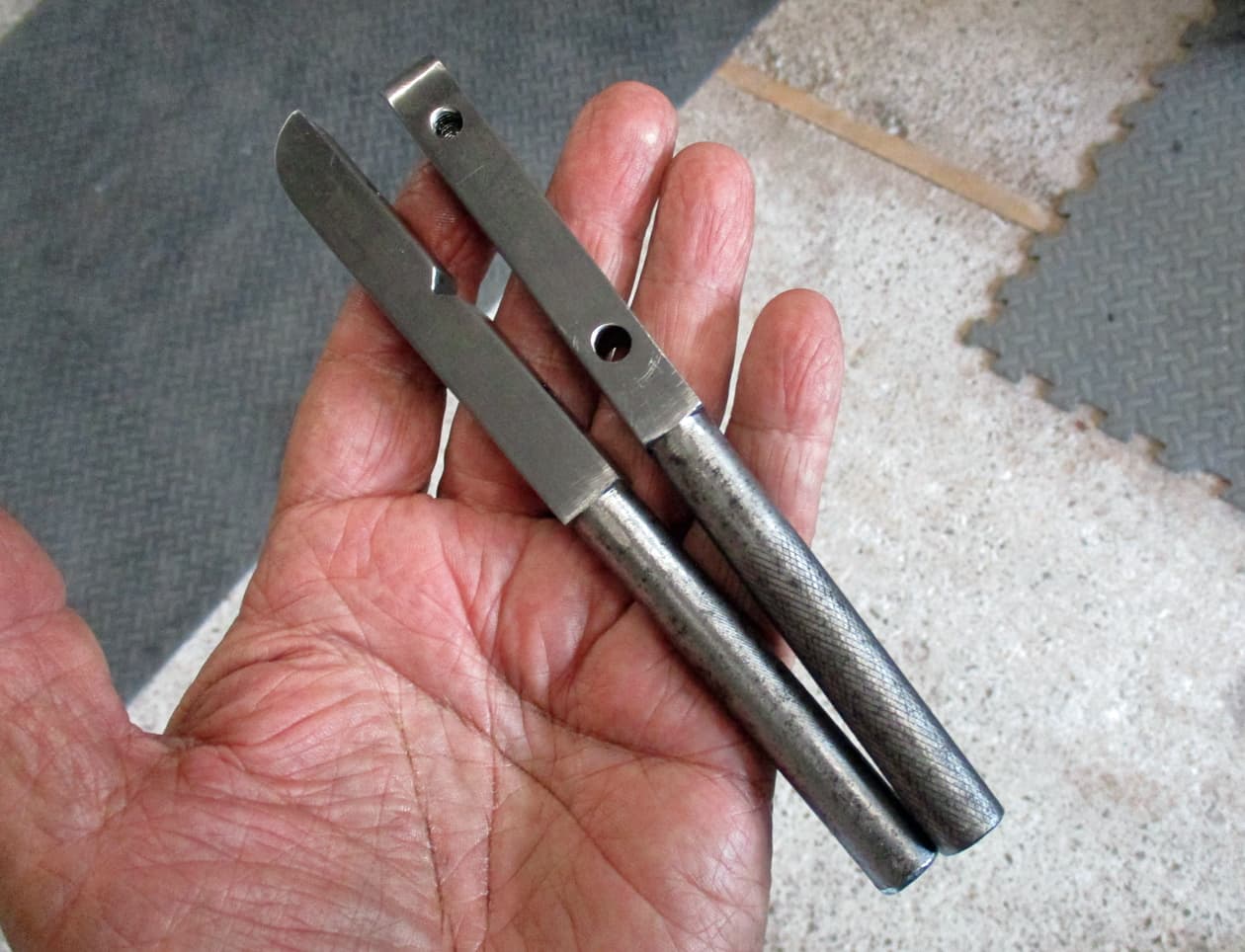
I thought it was homemade but the two halves are slightly different lengths and have different knurling on the handles.

Cleaned up, threads recut and new bolts.

Miles better than one of these and won’t break if given a bit of welly. Right, back to ordering spares.
Thankyou…welcome…over ![]()
12 Likes
We had to make our own as an apprentice
Ah, yes, that makes sense. Never thought of that.
Still awaiting stuff as Royal Mail isn’t so Royal these days. But things to do with the gear that is here.

Don’t get much for your several hundreds of squids these days.

Rebored or new barrels should have cross hatching to aid the new rings to ‘dig’ in and bed themselves. These are fine. A honing ball or stones can be used if reusing old barrels with new rings.
The honing stones should be 180 or 220 grit and are quite cheap from amazonian that fit into a drill and inserted into the bore. It is moved quickly in and out as it’s spinning to create the cross hatching.

Always give the bores a clean, and then clean them again. Spray brake cleaner onto a paper towel and wipe the bores out. If they are not going to be built or the engine kicked over for a while just wipe down with some WD40 to keep the surface rust monkey away.

Check that the parts delivered are the correct ones. This is the several types of pushrod tubes that Triumph have run over the years. I’ve had wrong sizes delivered in the past - which really gave me the hump when I was trying to use them on a build.
They obviously come in pairs. One supplier sent me one with a note that the other was on back order. “Jeez, where’s me money you carrot”.


Onto the piston and rings. There’s lots to check and fettle before fitting. T120 and T140 figures above, there’s also parts suppliers’ specs. Use the suppliers’ specs where there’s any differences. They normally don’t vary too much, question them if they do.

First is to make sure there’s some tolerance in the piston to bore sizes. Quotes are for top of skirt and bottom of skirt. Most builders will quote 4 to 5 thou. Any less and you risk a siezed engine. These are straight out of the box and are fine. Honing the bore further can make it all correct if they are slightly tight.

Then onto the rings. Don’t get all confused at this stage. it’s important to install the rings in the correct order and at the correct specification.
Each packet has a pair of rings. There’s a top, middle and bottom ring for each piston.
Just work on each one until it is fitted onto the piston in it’s correct position.

These are obviously Hepolite rings - others will have different markings (if at all) - so check the installation instructions that come with them.
This is the top ring showing an oval symbol on one side. This is to be installed towards the combustion chamber. ie this is the top of the ring.

The ring is inserted into the barrel bore. Rings are very brittle and snap easily as they don’t have much tensile capacity. Be careful when inserting or fitting over the piston.
Yes, I’ve broken rings, and it stings as rings only come in a set, you cannot just buy one.

Use the inverted piston to push the ring down the bore until you get it about half way down the gudgeon pin hole. The ring needs to be square to the bore to measure the gap correctly.

The ring in place with showing it’s end gap.

Use your trusty feeler gauges to measure the gap. Here, I’m going for about 15 thou. It’s not fitting the gap so it needs to be bigger.

Take the ring out and file one end of the ring down. There’s a hand wound special tool that goes in the vice and does this nicely but I just use a small file. File the end as square as possible taking off a small amount and re-try the gap down the bore. Make sure the end of the ring hasn’t got any sharp bits on it caused by the filing.

Slowly file until the feeler gauge fits. Lovely.

This is the second compression ring. This one is actually marked with the compression chamber oval and ‘TOP’ so we know which way that one is up. Do exactly the same to get the end gap for this one.

This is the last bottom oil ring. It comes in two pieces - the ring (which isn’t marked for top or bottom so can go any way up) and a circumferencial spring.
The gap in the ring really doesn’t matter on this one as the spring does all the work but I make it the same as the two top ones.

Once I’ve gapped the ring correctly, I then put the spring back inside it and press the ring to make the gap size. Here, there’s about three coils of the spring showing in the gap.
I take the spring back out and with some cutters take off three spring coils. I then file down the cut to make sure there’s no sharp bit and put the oil ring back together.

Before doing the remaining three rings put these ones onto the piston.

Fit one side gudgeon pin circlip into the piston first. Fit the inside circlip only so the gudgeon pin can slide in from the outside of the engine as it’s impossible to get the pin in from the middle of the engine.
I use the markings on the top of the piston (These have STD - standard - stamped on the crown) to read correctly from the back of the engine ie facing forward.

Once the circlip is fitted - I always, always, struggle getting new piston circlips in. The older ones with the rabbit ears could be inserted easily with a pair of pliers. I’m nervous about the screwdriver stabbing me (as it has several times causing liberal amounts of claret all over the piston) so it takes me ages to get them in - particularly after they’ve pinged off to the other side of the garage.
There must be an easier way.
Make sure they are properly in their groove. You really don’t want it to slip out when the engine is running, it just ruins your day.

First ring onto the piston is the bottom oil ring. This is positioned with the join in the spring opposite to the ring gap.
There’s a special tool that allows the rings to be opened up so they slip over the piston into position. I don’t have one - I spread the rings so they slip down into their groove. I don’t ‘walk’ them down. Spread them with your fingers and keep them level, a twist may cause a break. This is how I’ve broken them trying to ‘walk’ them in. Be careful, take your time.

Looking from above (with both pistons resting on the barrels with the gudgeon pins pushed partly in) the ring gap is at the front and the spring join is at the back.

Next on is the second ring. It’s gap is postioned about 120 degrees away from the bottom ring’s gap.

And lastly the first or top ring’s gap about 120 degrees from both the other ring’s gaps.
All done and ready to be installed.
Where’s that postman…
Thankyou…welcome…over ![]()
18 Likes
Just brilliant! I have fitted piston rings loads of times but still found that fascinating and a welcome distraction from the Wombles hitting a ball on the telly ![]() Cheers @Iron
Cheers @Iron
1 Like
Good stuff Iron, thanks for posting. Are you selling this bike?
1 Like
Probably/maybe, if/once I get it going. ![]()
2 Likes