T140e 1980

The cylinder head on T140Ds, T140Es and later models have parallel ports to accommadate the MkII carbs. The MkIIs were needed to meet the Sherman environmental requirements.
I’ve always liked the look of the splayed carbs on the earlier twins. Which is the main reason why I’ve never had a Bonnie later than 1978.

Although I’ve had the head vapour blasted and it looks quite good. It needs new valves and guides. However, the vapour blasted carbs (as seen above in the thread somewhere) are toast. well, the bodies could be used but the internals are long gone into the bin. I wouldn’t risk the bodies and would go for either new or a ‘pre-loved’ pair.

I’ve had this earlier splayed cylinder head knocking around for ages.

And I’ve also got this pair of Wassell concentrics that have been hanging about on the shelf.

The head will need new valves and new guides fitted but I’ll need them anyway.

The wassell carbs have chokes, the newer ticklers fitted and accessable pilot jets.

There’s also a new set of fittings in with the carbs. But no inlet manifolds.

Checking that the pushrods tubes fit either or


Looks like they will both work with the new pushrod tubes.

So, assuming everything fits I should save a few squids and, in my opinion, get a better looking hooligan.
cheers, ya’ll…and that :face_with_open_eyes_and_hand_over_mouth:

12 Likes

Aha, the postman came!

FFS, what is the point? I ordered a pile of stuff from this supplier including the bolts that go over these serrated washers. I ordered all the stuff together and they’ve posted just these on their own. Like I’m gonna need the washers without the bolts.
I expect lots of these dealers are just middle men ordering from others who then send the stuff out or are they really just potty like the rest of us.

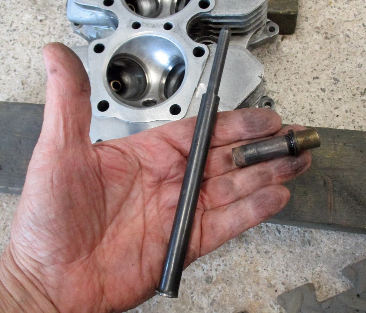
Ok, calm down and carry on. Gotta get the worn valve guides out so here’s the trusty Norman Hyde set.
I used to heat up the head to do this but there’s no need according to the instructions and it’s proved to be so on other builds.

Place the head on the floor (a bench just bounces when hit with a hammer) on some wood. Push the removal drift into the guide and using a reasonable sized hammer whack the guide out.

Like that.

All guides out. Notice that the zorsts side are longer than the inlet. Hotter see.

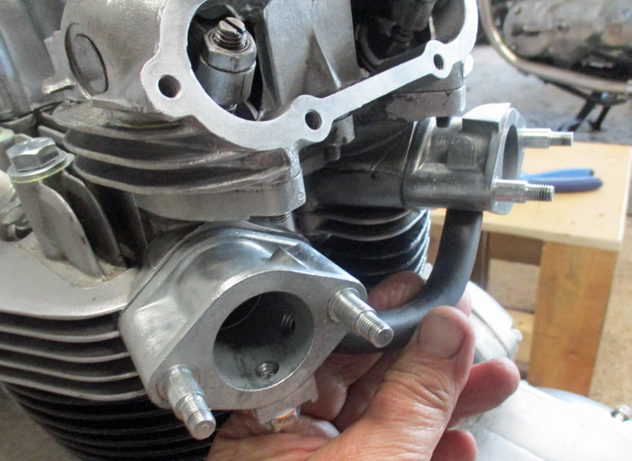
Onto cleaning and sorting the cylinder head. This is a regular sight on Triumph cylinder heads. Notice how the head bolts have made indentations into the alloy.

Here’s one of the old washers placed back into the indentation. It’s been pressed into the alloy due to overtightening of the cylinder head bolts.

This happens because the engine has either not been built or maintained correctly.
Cylinder heads are usually made of an alluminium alloy that is relatively soft. The specified torques on the head bolts are pretty low in comparison to everything else.
In the T140 specs they are 16 ftlbs and 18 ftlbs. The T120 specs were reduced from 25ftlbs.
Older T120s have 8 head bolts, late 60s have 9 head bolts and T140s have 10 head bolts. This was partly to try to keep the torques down but also to enable the larger diameter bores from 650cc to 750cc.

The head bolts are required to be re-torqued during running in and also at regular servicing. People without a torque wrench would just think “blimey, these are a bit loose let’s lean on the spanner”

There’s a pushrod tube running up from the engine cases to the cylinder head in the middle at the front and back. These are well known oil leaks but also act as a strut that will hold the middle of the cylinder head while the over tightened outer headbolts will pull the head down and warp it. The warping can also be caused when the wrong thickness oil rings are used on the pushrod tubes.

So, our owner will now spot a head gsket oil leak wetting the fins on the barrels. Out with the spanners and tighten up those head bolts.

For all those reasons, a really clever change was/is to install these larger diameter washers. These help spread load across a slightly wider area.

All the rocker box gaskets are made to allow for the larger diameter washers. I always use the metal inpregnated gaskets on the rocker boxes as they work really well.

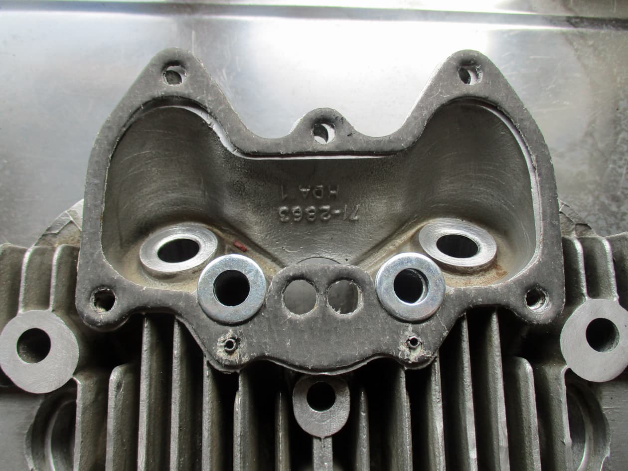
Here’s the head showing all 10 head bolt holes. Rather than just putting the larger diameter washers on when rebuilding some attempt should be made to flatten the area so the washers can spread the load.

You can see where I’ve removed the indentations from the four outer holes by carefully filing them flat again. This is pretty easy to do with a long flat file using the fins and the top of the head as a guide.

The proper thing to do would be to take the head to an engineer and get him to spot mill the washer areas. I’ve managed previously to carefully file them down with a flat drill piece and wet n dry.
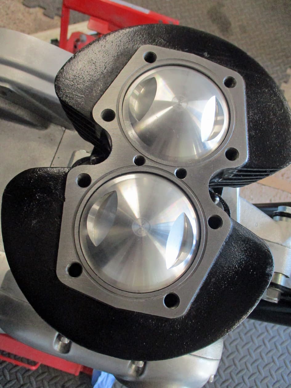
But now I have a pillar drill.
I also found I’d got a milling head thing in the box with all the drills that came with it. So clamped it onto the bed of the drill. Very carefully positioned the drill and very very slowly took away material until the washer areas were flat.

Quite pleased with that, I think.
Thank you…over… :stuck_out_tongue:

11 Likes

What to say? Just in awe, really.

3 Likes

Bloody amazing :heart_eyes:

1 Like

A few more bits arrived. Delivery now seems to be delayed on everything :neutral_face:

Two tappet guide blocks, o rings, set bolts and four tappets. Once installed, those’ll allow the barrels to go on.

Here’s an older years’ tappet guide block in comparison. The older design cannot be used as the pushrod tube won’t fit over them. So, new ones it is.

Here’s the first issue. In the exhaust side tappets there is an oil hole which allows oil to come up from the crank, horizontally through a drill hole in the base of the barrels into the slot in the side of the tappet guide block and down the centre of the tappet.
It’s only done on the exhaust tappets as they get a bit hot.
A lot of builders (and indeed later than 1979 Triumphs did away with this as apparently it wasn’t needed) block off the oil feed from the crankcase and use barrels without the drilling and use the plain guides and tappets. I stick with the original design and keep the oil feed.
However, if the oil hole through the tappet is blocked then what’s the point?
So i had to clean that out with a strand of wire.

You can see on this tappet block where the oil moves round the slot, through a hole and down the tappet. So the tappets have to slide into the block with the single hole facing outwards.

And here’s the next issue. I can hardly push the tappet into the guide block. These need to rise and fall on the cams, work the pushrods to move the rockers which operate the valves.
They really need to fall under their own weight in and out of the tappet block.
A bit annoying that new ‘quality’ parts just aren’t fitting.

A normally easy job just got a bit more testing. So, went and ate my lunch… :neutral_face:

6 Likes

Food and a large cup of tea aids everything…

I thought of using a reamer but I didn’t have one of the appropriate diameter so I selected a long bolt just under the tappet hole diameter in the block. Threaded the bolt through the tappet block and attached a drill.
Took my time applying valve grinding paste to the bolt and running the drill while I pressed the block onto the bolt while it span.
It took a lot more ‘grinding’ than I thought it would. I kept trying the size by cleaning the block off and running in the tappet to feel for fit.
Once the tappets fell in and out of the block under their own weight I gave everything a thorough clean - don’t really want grinding paste in there.

This is the special tool to install the tappet blocks into the barrels.

Make sure the tool fits through the hole that’s going to take the block. Otherwise the tool gets jammed in the hole.

Like this one did some years ago and broke the tappet block getting it back out. I then grinded it down to suit - even the pegs needed grinding - that’ll teach me to go all cheap and nasty. Invest in good tools where you can. Are you listening Father Christmas? I’ve been good…

Line up the tappet block’s hole with the hole in the barrels to take the set bolts. This makes sure the tappets run perpendicular to the cams.

Insert the special tool and slowly hammer the block into place. It makes a different sound when it’s home. No need to hurry, no need to use a sledge hammer - the blocks are breakable if pounded on.

Make sure the holes line up. If not, use the special tool on the other end of the block, hammer the block out and start again. The set bolt will not pull the block round to the correct alignment, tightening it up will just mangle up the bolt.
Use some locktight on the bolt - I only ever use blue locktight - the red locktight will only cause issues with dismantling in the future.

The block will be squeezed slightly by pressing into the barrels so check that the tappets are still free to fall out under their own weight.
Do it all over again for the other tappet block.

As the tappets can fall out they need to be held in place while the barrels are installed over the pistons. I use cable ties, others use some small pieces of fuel/oil rubber line but they do need holding with something while concentrating on the barrel install.

10 Likes

Slowly slowly catchy monkey

2 Likes

And, at last, onto barrel install

Protect the crankcases from anything falling in there. And get the pistons on by threading/pushing in the gudgeon pins into the conrods.

Always use new piston circlips because all the books tell you to. Even though the ones that came out look ok. I keep the old ones in a little drawer for some reason, I’ve got loads of old ones. Why’s that then?..I’ve no idea

This is easy to do if building the engine on the bench. But is really fiddly with the engine in the bike - prbably because I really didn’t want it to ping across the garage and I really didn’t want to stab myself. But check they are in the groove once they are in.

These are the ring compressors. For these pistons I use 75-80mm. They come in different sizes. They make this job a lot easier than trying to threadle the rings in one by one as the barrels go on.

Tighten up the compressors over the rings all the way and slacken off by a couple of turns. The made up board under the pistons stop them moving down while the barrels are pressed on. A coiuple of bits of wood placed across the crankcases will do - probably better than what I’ve been using for ages as this time it flapped about all over the place.

Don’t forget the base gasket - oops :stuck_out_tongue_closed_eyes:

Place the barrels over the pistons while looking down the bores to make sure they are over centrally. Be brave and push the barrels down over the rings.

Easy peasy. Well, it didn’t work the first two tries. It usually works ok on the bench but it took three goes this time. Take off the compressor rings and push the barrels down over the studs. A few taps with a rubber mallet may be needed to push them home.

Nip up all the nuts. The 12 point nuts require a special spanner. But they are hard to find and quite expensive. So grind a slither off of a half inch ring spanner and it’s good to go.
Turn the crank over with a spanner and enjoy watching the pistons and tappets move up and down.

Tighten up and wonder how the morning job suddenly turned into an all day one.
Over… :face_with_open_eyes_and_hand_over_mouth:

15 Likes

This is a check that all vintage twin Triumph rebuilds require before fitting the cylinder head.

This is the pushrod tube and fittings required for a T140E, the designs changed through the years as the pushrod tubes were notorious for oil leaks.
I hasten to add that badly built or non-maintained engines did have pushrod tube problems. A properly built engine will not leak. Triumph paid too much attention to moaning minnies and dedicated scarce resources to so called ‘warranty issues’. But all that’s another very long story and as this build is going on long enough we’ll leave that there.
Other models and years machines had different o rings etc etc so the parts book is essential for the correct parts.

Pretty simple on the T140E, slip one of the o rings over the tappet block

Slip the wedding band over the o ring and block, ensuring the o ring is sitting down on the block shelf.

Place the push rod into the wedding band pushing on the o ring.

Put another o ring over the top of the pushrod.

Do the same for the other pushrod fitting and place on the cylinder head gasket. This head gasket is a composite type that I’ve not used before.

As the composite is quite thick (they compress down so re-torques are required) but did solve the headgasket leaks when they were introduced in the late 1970s. I’m going to use an old copper gasket to carry out the check measurements.
Lots of people swear by the copper gaskets but I’ve only ever had trouble with them but use whatever floats your boat.

Place the gasket and push on the cylinder head. Do not install any bolts but make sure the head is pressed down firmly over the pushrod tubes to push the or ings into place.
There will now be a small gap between the head gasket and the cylinder head. This is the amount of ‘crush’ that will be applied by torquing down the head bolts onto the o rings at the top and bottom of the push rods and onto the head gasket.

Every so often a piece of advice was issued called a service bullettin. These were mainly issued by Triumph USA as their customer service was (and still is) much better than ours.
As you can see the ‘crush’ was advised to be 1/16 of an inch. That’s about 60 thousands of an inch or about 1.5mm.
There’s a couple of issues here trying to be alleviated, enough crush on the o rings and head gasket so they don’t leak (oil and/or hot gases) but not so much movement so that the cylinder head is actually warped over the pushrod tubes.

I’d rather the leak than the warped head so I go for a crush of between 40 to 60 thou. Here’s my measuring sticks.

Measuring the ‘crush’. It’s not that easy as the head will tilt like a seesaw on the pushrods so a sort of guesstimate is made with the head held onto the pushrod tubes. But that looks good enough to me.

Older variants may require adjustment of the sealing o rings as they do come in different thicknesses - the green ones are paper thin for the Triple engined T160 and BSA A75 Rocket Threes. While the white silicon rings come in several thicknesses depending on what your crush measures.
Head skims will also cause issues that will perhaps require thicker head gaskets that are available. Thicker head gaskets could also be installed to reduce compression.
In all cases careful measuring and correct crush is needed to ensure a well built engine. So there…

Thank you…welcome…over :face_with_open_eyes_and_hand_over_mouth:

14 Likes

Would 2 sets of feeler gauges help to get bilaterally even measurements? (And counter the see saw)

2 Likes

Good thinking. I reckon i may have another set banding around here somewhere, I’ll have another look at that in the morrow. Thank you :slightly_smiling_face:

3 Likes

Have found some more feelers gauges and although I needed three hands it all looks good.

Now i’m pretty sure the older early 70s cylinder head is going to be fine, the new valves need to be ground in.

First the new guides go in. Using Norman’s insertion puller tool thing.

Thread the tool in from the underside (I’ve had to stick the mushroom section onto the bolt and cut a slot in the top of the bolt to stop it occasionally spinning in the valve seat. Usually it’s fine but that sorted it).

Threadle the new guide over the bolt. Long ones for the exhaust side. I start with the long ones as this process takes a bit of muscle so I leave the easier ones for later.

Assemble the rest of the tool and use a long ring spanner to turn the nut to press the guide into the head.

The guide will make loud cracking noises as it is pressed into the head. First time I heard it I thought I’d broken something as this really takes some work to get them in.
I’ve thought about using the impact driver but I think slowly by hand is the way. I could heat the head up but Norman reckons it’s best to do everything at room temperature.
I used to boil the head, freeze the guides and use a lump hammer to drive them in but I think this erm…less violent method is better.

One done, three to go :slightly_smiling_face:…over…

12 Likes


The valves fit perfectly in the guides. Sometimes they’ll need a bit of reaming, mostly when manufactured or supplied by different people.
These fit lovely, smooth and fall under their own weight into the seats.

However, they will need to be ground in to make as good a seal as possible.
Gather up the gear needed, some grinding paste, coarse in one end of the tin and fine in the other. And a selection of sticks with suckers on to hold the valves.
This is a fairly simple operation but is pretty boring and can be bloody frustrating when the suckers keep coming unbloodystuck.

Doing the job really properly involves having new valve seats installed and cut to the new valves. This allows for the lean engine burn these days with unleaded and ethanol fuels.
I’ve never had new seats installed unless the old ones are properly buggered. The bottom of the valves should sit just proud of the seats, if they are getting flat or are sinking down into the seat then it would be worth getting an engineering place to install new ones made from the right materials.

I only very rarely use the coarse paste - I’ve had valve seats rusty and used it there - but normally the fine paste will do.
Stick your suckerstick onto the valve with some spit. And add a small amount of paste around the rim to be ground.

A touch of oil on the valve stem put it back in the guide and go to work on the stick like you are lighting a bonfire on that desert island. Every so often, pull the valve out and give it a bit of a turn so the paste is moved around the whole of the rim.
You can hear when the paste has done it’s thing. Take the valve out and apply some more paste from the tin.
Do this over and over aboput 4 or 5 times.
Be careful not to get any paste anywhere other than the valve and the seat as you don’t want it wearing the guide out prematurely.

Give evrything a good clean to remove all the paste. The valve rim should look like this - matt grey where the paste has done it’s job. Notice how the wearing edge hasd been ground right up to where the valve surfaces change direction.

Here’s the valve seat showing the same matt grey where it meets the valve. The areas may differ from engine to engine. But you are looking for a good seal against any gases escaping while the valve is closed.

I never use this any more (mostly because I can’t open the bloody stupid tin) but if you have any doubt…

…apply a thin layer around the valve seat. Put the valve back in and give it sevral complete turns on the suckstick…

…they’ll be no blue left on the touching surface. If there’s a low spot then there will some blue left behind. So, start the whole grinding work again on that valve and seat until the whole circumference of the seat is touching the valve.

As each valve grind is completed mark up the valves with which one it is. It will need to be installed into the seat it was ground in.
Mark them up as you do them as they need to come out to continue with the next valve.
To just check that they seal properly you can pour some deisel, petrol, paraffin, tea etc into the combustion chambers (obviously after inserting a sparkplug so there’s no big hole) to see if it stays there.
I’ll leave that test to when the valve springs are all in place.

laters ya’ll…over :no_mouth:

14 Likes

Install the valves etc. Ariston and on and on…feels like it’s getting a bit much now gang :roll_eyes:

Valve and bottom cup go in

Two new springs

Top collar and hold it all together…

And into the spring compressing clamp - cheap as chips on amazonian

Compress the spring using the widest collar in the clamp set to give some room to get the collets in. These can be a bit of a fiddle so I’ve found that one of those long magnets on a bendy spring thing help.

Make sure the collets go under the lip in the valve stem thin edge downwards. Then undo the clamp and everything slips into place. Give the valve stem a couple of whacks with a hammer to move the valve to make sure everything is seated and tight.

Add a valve stem oil seal to the inlet valves. These help stop oil being sucked down between the stem and the guide. The inlet valve opens as the piston is falling to suck in the fuel mixture, we’d rather it wasn’t sucking oil in from the rocker box as well.
The oil seals are not needed on the exhaust valves as they open when the piston is rising to blow the exhaust gases out. So the pressure tends to keep the oil out anyway.

Once all four valves are installed then test for any leaks. Put a couple of sparkplugs in.
Probably best to use paraffin or diesel or petrol but here I used water from the water butt just outside the door. I was going to use my tea but I’d drank that.

I left the water in while I went off to make another tea. All looks pretty well watertight. Done, good…thank you…over :no_mouth:

9 Likes

A whole new headbolt set

None of them would thread in by hand :unamused:

The threads look like poo too. I assume these have been rolled in rather than cut.

Quite a lot of material came off of some of them but at least they would now actually screw in.

Note the blank end on some of the studs. These are to allow the studs/bolts to bottom out in the hole without putting a compression on the surrounding material of the barrels. So the nipple/blank section goes downwards into the barrels.
I’ve seen some actually drop small ball bearings into the bolt holes in the barrels just to ensure the studs exert no pressure when expanding due to tightening.

Did the two feeler gauge trick as suggested by @DCS222 and it worked a treat, ta.

Re - installed everything but this time a smear of clear silicon to the o rings and joints in the pushrod tubes.

Push on the cylinder head

Using that Duralac compound that some of you suggested to stop the steel welding itself to the alloy on all the bolt shafts

Screwed everything up finger tight only.


Check the specs again on the torque requirements. Confirmed with my scribbles in the workshop manual.

Searching through the special tools drawer for the little allen bolt thing that allows the allen headed bolts to be torqued

Aha

Here it is. Because the engine is in the frame there’s limited room between the head and the top tube so this little handy whatsit just gives enough room to use the torque wrench.

All torqued up in the correct sequence. Put some sparkplugs in to stop the earwigs/spiders/gremlins getting in there.
That’s that until next month’s pension :neutral_face:…thank you…over…

11 Likes

Catching up on a few ancillary parts while I wait on a complete clutch set up. (I robbed the clutch out of this one for another bike so everything has to be replaced.)

Outer gearbox cover rebuild. There’s a weld around the kickstart spring anchor pin. I’ve no idea how this could have been broken unless the kickstart quadrant was installed incorrectly and someone’s over enthusiastic kick broke it. The weld looks ok so we’ll stick with this one.

Can’t remember if I showed the clutch lver assembly rebuild above. But it has been taken apart cleaned inspected and re-assembled.
It’s basically two plates with three dents in each side. In the dents are three ball bearings. When the front plate is pulled on by the clutch cable the plate rolls the three ball bearings to push the plates apart. That turns the clutch lever pull into a sideways push onto the push rod. The push rod pushes the pressure plate that releases the clutch springa and allows the clutch plates to separate. Sorry, Grannies and Eggs.

Took me ages to find the original countersunk screws. The ordered new ones just didn’t arrive and I was fed up with waiting so got me money back. So a bit of a clean up, some blue locktight and sorted.

Install the gearchange quadrant making sure all is clean and oiled up.

New springs in comparison to the old ones. The old ones looked and felt ok but forming a shorter memory.

New guide plate as the old springs were rusting into the original.

New plungers and springs

All assembled and bolted up. Don’t be tempted to try the gearchange movement as the plungers will just ping out and stab you in the eye.

Reusing the original kickstart assembly but ensure the spring is located correctly as per diagram in the workshop manual. This may be why the original pin was broken as it needed changing from what it was.

Temorarily put the kickstart lever on to allow winding of the spring and assembly back onto the engine.

It all needs to come apart to index, sort the kickstart drive and seal everything up with gaskets etc. But I’ll wait until final build for that.
Thankeee…over…

13 Likes

A few odds and ends

New intake manifolds and balance pipe connectors. Connectors go in with some blue locktight.

The bracket for the choke handle isn’t going on so filled that with a shortened bolt, copper washer and some gasket stuff - leaks not required thank you.

New gaskets and bolt set from stash, new balancing hose cut and pressed onto connectors.

Throttle and beston style grip fitted - used some carb cleaner as a lubricant as it evaporates quickly and leaves no residue. Blimey, it’s bloody cold though!!! :innocent:

And on the clutch side. Remembered to slip the Amal clutch lever on first as it doesn’t come apart.
Planning on a seven plate clutch so no need for adjustable levers or Charles Atlas - I get sand kicked on me all the time, so I don’t go near the beach. Over…

8 Likes

Let’s have a look at those carbs I’ve had hanging around for a while

Ah, yes Wassells. I’ve not had these before (other than the bike I obviously took these off of - I can’t remember which one it was). These sell quite well I think as Amals are harder to get hold of.
Amal seem to sell to dealers who have standing block orders so it’s not often they are available on the Amal site. Burlen of Salisbury own Amal now I think.

This is nice. The pilot jets are removable rather than just a screw that allows access for cleaning. They have the new longer ticklers which is an improvement as well.

The slides are nice too compared to the originals. But we’ll ditch the choke enricher slide things.

Removing the choke cable leaves a big hole in the carb cap. So thread the hole and insert a short bolt and seal it up.
Take the carbs apart and give a proper clean to all jets, floats, bowls etc. These had the Amal plastic floats and needle valves so replaced the needle valve with new viton ones.

To mount the carbs I use the fatter o rings to help stop the carbs clamping to the manifolds and getting hot. The fatter ones also allow some movement and protection against vibration apparently.

'Cause the o rings don’t sit in the groove I stick them in with some grease to stop them falling out while assembling.

All assembled but again I don’t like the split throttle cable - they never seem to pull properly in my mind. (UK bikes were supplied with the split cable but US export bikes all had the twin cables.) So I’ve ordered a twin cable twist grip and cables. I’ll redo when they arrive.
Note the extensive air filtration system :stuck_out_tongue_closed_eyes:
Thank you…over… :no_mouth:

12 Likes

Always enjoy these thread updates, the best.

5 Likes

Started thinking about the electrics :face_with_spiral_eyes:

thing

Always trying to make the builds better so bought one of these. 6 fuses that light up if they blow.

Looks like the best place to mount is under the seat cowl. So marked, drilled mudguard, made the cowl opening a bit larger and stuck on some rubber edging around the hole. All fits nicely.

Except the mudguard isn’t flat so cut some thick rubber washers out of some oil pipeline.

And all mounts up snug as a bug.

Stickers are supplied with the unit to identify the fuses. I’m going with the usual basic electrical equipment on a T140. :neutral_face:
Over…

9 Likes