Very cunning, “Baldrick” … ![]()
2 Likes
Yep , that’s a Cunning Stunt .
2 Likes
2nd prize?
1 Like
You’ll have one prize and like it! ![]()
1 Like
What each?
1 Like
Spares are arriving in dribs and drabs so we’ll sort the dribs out

Double pull twist grip throttle. In bits to install.

The twist grip casting is full of flash, sharp edges and just slightly too small to allow the nipples to swivel easily. So it all needs to be cleaned up with small files so cables aren’t going to fray or get caught up and jam. Takes a bit of time but worth it.
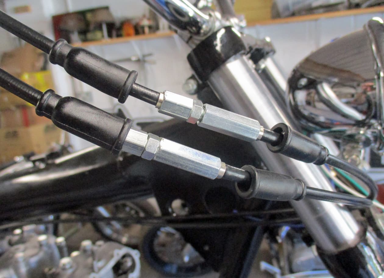
Make sure the cables are adjusted to give as much slack as possible for fitting into the grip.

Nipples and cables slip in easily now.

Whack in a finger full of grease…

…bollox, forgot to take out the stupid cruise control pressure thing. They can be left in but they nearly always restrict movement of the twist grip so they need to be squeezed and closed up.
I just take them out (the bolt that operates the pressure is hammered over like a rivet and can be a right arse to get out - this one fell out, quality stuff, pffft.)
I used to use these as they allow the throttle twist grip to be held by the bolt on the spring clip thing. But that was when the bolts were attached to a bigger diameter knob - the knob came off and I had a bit of a panicky moment once - so I just bin them now and have to hold the throttle at all times. I just use my left hand if I need to adjust my tie these days. ![]()

Slip the twist grip onto the handlebars and put the bolts in just to hold it together. Then insert the ferrules over the cables.

Do it all up tight and make sure the throttle turns easily and the cables are pulling the carb throttle slides. Make sure the throttle slides are allowed to close all the way in the carbs when letting the throttle off.
Put a finger into a carb to hold the throttle slide up and listen for the other slide making a noise as it hits the bottom of it’s run. All ok, check the other carb.
I’ll do the final carb syncroing later on. No need for carb balancing equipment. So that’s that drib done.
Over… ![]()
10 Likes
So, moving onto the primary side

The chain tensioner is a bit of a faff to install with the gubbins all in there so may as well put that in.

These are the usual parts to install.

The new tensioner blades always need to be widened up a bit to allow the trunnion bits to slip in, so do that with a suitable sized screwdriver.

And the adjuster screw is too big to slip into the casing! what what ![]()

And the abutment would normally have a slot to allow the tie rod to be inserted! what what what…???

Best check the parts catalogue…Here’s what I was expecting

And here’s what it should be on an E model. Damn, it’s a change in design I never noticed.
I can see why as the usual way was to take out a bolt from the casing (that was really difficult to stop an oil leak from and could easily be over tightened sometimes cracking the casing) and fiddle around trying to insert a screwdriver to turn the adjuster to tighten up the primary chain.
This version looks like the bolt has another bolt through it that then pushes on the blade - rather than tightening up the tie rod - to bend it up and hence tighten the chain.
Ok, I could machine down the adjuster and make it go through the smaller casing access to make it work the old way or go order the correct parts.
A search on line doesn’t give much hope on finding the parts but a small cell in my brain tells me I may have kept something from the original boxes of parts…

Hafuckinha…I knew it!!! I didn’t know what this was so put it into my little drawer of picky hitty things that may come in handy for some odd job or other.

And searching through the stack of old rusty nuts and bolts that came with the bike found the other parts missing. Result ![]()

Gave the tie rod a bit of a clean up and it slipped right in. But thinking about it, the parts catalogue shows it the wrong way round - the thicker section needs to be pushed on by the adjustment bolt.

A bit of a fiddle to get the trunnion over the tie rod and then the blade over the abutment but eventually got it all sitting nicely.

These adjuster parts then need a clean up and fitting.

Well, what an arse that was! It would have been easy with the engine out but a right faff to fit and try to tighten up with it all in the frame. This may be a potential oil leak area as tightening anything up is almost impossible. We’ll see what this brings in the future.
Thank you…welcome…over ![]()
9 Likes
Moving on and continuing in the primary side

Later than 1969/70 engines have a row of three little holes that connect the primary with the crankcase. Earlier engines used different oils in the clutch side and the engine that were separated by having an oil seal around the crankshaft. These later dated engines use engine oil in both sides.
The holes keep the level correct in the primary/clutch side.
The breather on the later engines can therefore be in the primary side while earlier engines breathed through a timed valve on the end of the inlet cam.
So no need to seal off around the crankshaft but the big hole around the gearbox main shaft (that gives access to the front sprocket) needs to be sealed off with the clutch cover plate.

The cover plate was never found in the box of bits so a new one was ordered along with new securing screws, gasket and oil seal for the main shaft.

The oil seal goes in first. Asd with all oil seals the springed open end of the seal needs to point towards the oil being sealed off so that’s the way it needs to go in.

Using a suitable drift bash it into place so the back is level with the plate.

Whack some sealer around the hole to hold the gasket

Stick on the gasket

Put a dab of oil on the main shaft (to help the oil seal on) and push the plate into place. Use some blue lock tight (don’t really want one of these coming loose in amongst the clutch and primary chain) screw in the securing screws. Tighten up in an opposite sequence to ensure the plate stays flat.

All in place. The nut and stud have been removed from the crankshaft to allow the primary/clutch to be installed. They were only in temporarily to allow the crank to be turned over to move the pistons.
Clutch next…such fun…over ![]()
11 Likes
The DHL delivery man and me have an understanding…

Most of the clutch parts, not all. But there’s a check that has to be done before final installation so we’ll get on with that.
The correct alignment of the crankshaft sprocket’s teeth with the teeth on the clutch basket is essential to ensure there’s no premature wear. It’s not difficult but should be done.

New woodruff key…

…into the main shaft. Tap it in so it’s parallel with the taper on the shaft otherwise it has a tendency to slip out of the slot due to it’s curved underside.

This is the new clutch hub, it has a tapered central hole with a slot for the woodruff key.
A note on this for info: I robbed the original one off this bike (which was in good condition) to use on another build as that one’s hub was manufactured incorrectly. It took me ages to work it out (some of you may remember from that other place where I detailed that build) The taper was machined just off so that the hub did not push far enough onto the mainshaft. For some reason the PO of that bike thought the solution was to grind off the back of the clutch centre to allow the clutch to turn freely as it must have hit the primary cover. Jeez…the moral of the story is to buy quality parts or at least try to figure out what’s wrong before getting out the grinder to attack major components of an engine.

Always use new rollers when building a clutch - they are inexpensive - 20 are required.
Use lashings of grease around the hub’s bearing race…

…and stick on the roller bearings.

Put the thrust washer over the roller bearings with the brassy/copper coating upwards (some will be the same on both sides, some (like this one) has one steel side.

Slot the clutch basket over the rollers. It’s a tightish fit and has to be placed over squarely. For fun, give the basket a spin to watch the rollers working. ![]()

This is a complete clutch centre that is supplied already built. The centre can be built up using each seperate part or rebuild an old one installing new drive rubbers into the spider. The rubbers are quite difficult to compress to build up the centre and a special tool needs to be made up to do this.
As I had no existing parts available I just bought the already built up complete centre, so there.
Insert the three clutch spring screws (note the squared heads so they don’t turn once in place) from the back side of the centre.

And while holding the screws, so they don’t fall out, push the centre onto the hub.

New ones nearly always need some help and can be difficult to locate the splines. Some generous tapping with the mallet helps.
Unbelievably they will pull off really easily when trying to install the completed primary chain later on and can cause a slight bit of annoyance. Be prepared for this and accept it as melding souls with your new rebuilt Triumph. (Melding???)

Check the back of the basket to ensure everything is tightly together.

Push the completed basket onto the mainshaft ensuring the hub slot fits nicely over the woodruff key. Use a torch to make sure you can see the key is still sitting in it’s slot in the mainshaft. They move up very easily and will jam onto the oil seal. Make sure you check, even if you take the basket off again if there’s any doubt.

Put in the big fat washer…

…and the locking nut.
On older motors there is a nut with a locking tab. The tabs can be misaligned fairly easily and are a bit of a git to fit as the tab is quite difficult to bend over as it sits quite deeply in the recess. Get a new locking nut or just leave out the tab washer while checking this alignment - put it in on the final build.

This will be confusing if you are following along with a parts book. This is the engine sprocket stepped spacer. The stepped part goes inwards towards the engine.

And is not shown in any year of the T140’s parts catalogues. Which could be a problem if you discover you have some parts left over on an engine rebuild or are building an engine from parts.
The stepped spacer is 90 thou thick and is part number 71-2663. The spacer pushes the crankshaft sprocket out to align it’s teeth with the clutch basket teeth. Well, it almost does…

…there’s also a selection of shims available in 10 thou or 30 thou thicknesses.
Or, if you are rebuilding an engine there may have been shims already in place. Reuse those if they are in ok condition. But it’s worth having a selection just in case they are needed.

Install the crankshaft sprocket with the longer centre inwards towards the engine.

To carry out the checking the clutch basket really needs to be secured as it tends to move about on the taper.

To do the centre nut up the clutch locking tool is used to lock the basket to the centre. Or an old plain steel clutch plate can be drilled and bolted to an old friction plate to make up a locking plate.

To stop the basket turning wedge a hard rubber vice jaw or something similar that won’t cause any damage inbetween the basket and the casing. Do the centre nut up just to hold the basket in firmly, no need to torque it right up to the spec just pinch it up.

This is the method to use to space out the front crankshaft sprocket.
A steel flat is used pressed up to each side of the crank sprocket at A and B. Then look at any gap - or lack of gap - at C.
Both sets of teeth need to align to ensure the triplex primary chain runs straight. Shims need to added or removed to achieve this.
Engines being rebuilt using existing shims are usually ok and align fine.
To insert/remove shims or even if everything measures fine, the crank sprocket and clutch basket all needs to come out again. This is because the primary chain is a continous one and cannot be installed with the sprocket and basket in place.
Don’t think that the teeth alignment can be checked with any accuracy with the chain in place - they cannot - do it properly lazy bones.

So, take it all out again so the whole thing can go back in with the correct shims in place.
Thank you…over ![]()
9 Likes
Always a lot more odds and ends to do than you think.
Rebuiilding a bike has the advantage of seeing what’s what as it comes apart - all the bits are there, any that are to be binned can be listed and ordered as they are needed, or not, as the case may be.
Building a bike, custom, chop etc is another matter as a lot of the parts are only envisioned as the build progresses.
Expect to lose a lot of time when things don’t work, parts are ordered that are needed for the build to progress - most parts just aren’t available in the local garage.
Sleep will be lost while imagining how the engine will drive the back wheel, how the brakes will operate, what to paint on the tank, what’ the sissy bar will look like, how to mount the mudguards etc etc.

Ignition switch. Where to mount and how to mount.
This is a three way, three wire switch. OFF - ON - LIGHTS. Keep it simple stupid (I like to turn the lights on when I want them on as I might be hiding or it may be sunny).

Had to mount on the inner gearbox as the swingarm/engine plate mount I normally use is taken up by the rear brake stay due to the caliper being above the brake disc on these later models.

Carrying on with a touch of wiring. I’m redrawing my wiring diagram to suit my new and improved fuseboxed version.
Once I’ve done the drawing I’ll talk about how I tackle the wiring on a custom build.
It’s something I could never fathom but I saw how bad some local custom builders did theirs so I tried to think it through and now do it for myself.

Lots of little things need to be sorted. I temporarily laced up a chain to check the sprocket alignment and noticed that even though the correct parts were ordered a ‘normal’ nut and bolt is supplied. It’s a bit close to the chain…

…so take it out and cut a bit off.

Sorted. Just needs dressing up a bit so I don’t cut my fingers off on it.
Thankeee…over ![]()
12 Likes
A quick tip while I’m thinking about it

A pair of Beston style grips came today and slipped them on.
The easiest way of getting these on is to push them on the bars a little way - no twisting cause they need to sit straight or they look crap.
No fairy liquid, no oil, no glue.
There’s a little hole in the end of the grips, Put your finger over one and stick the compressor hose on the other grip’s hole at the other end of the bars. The grips will partly expand and can easily be pushed on to the bars.
You may require someone else’s finger when finishing off the twist grip as you don’t want it too far so it rubs on the handlebar mounting.
Cool eh? Thankyou…welcome…over ![]()

Bugger, there’s another thing I’ve got to buy…I thought I might be able to reuse this one, oh well, it saves me putting it on, finding out it doesn’t charge and then having to take it all apart again.
9 Likes
Breather cover plate came so tried it in place.

Got two, one for the stash.

Cleaned up nicely and goes in easily with a new countersunk screw and alternator wires sleeve nut and grommet.

Not much point having the rubber hose (arrowed) as there’s no hole for a clip to hold it (also arrowed) to run the oil onto the crankshaft primary sprocket.
There’s discussions that the sprocket is oiled by the primary turning and splashing oil all over the place so no need for the rubber pipe.
I’m in two minds as there’s not that much oil pouring out when running the bike up and checking the timing with a strobe through the open access in the primary cover.
There’s also the fact that this bike obviously wasn’t maintained that well - particularly oil changes - and the front sprocket is perfect with this shorter oil pipe.
We’ll leave well alone I think…over
9 Likes
A bit of a fiddle now to get it all together as this is a job for 3 hands

Assemble the front crank sprocket, primary chain (this is continuous so it all has to go on at once) and the clutch basket

The footchange spindle (the rod that crosses the engine to allow a designed right hand gear change engine to be controlled from the gear change pedal on the left side) is inserted but not pushed all the way in to allow the basket to be placed in the ‘U’ bend section

Make sure the woodruff key is firmly in the slot on the mainshaft…

…as this can easily happen.

Make sure the correct shims are in place as measured for above on the crankshaft.

Lift the whole primary assembly into place. Now this can be difficult but take your time.
The clutch basket is positioned into the ‘U’ bend on the gearchange spindle, while the front crank sprocket is slipped onto the crank shaft, while the primary chain is lifted at the bottom to slip over the tensioner blade.
All the while ensuring that the clutch centre doesn’t push the woodruff key out of the mainshaft and aligning the spindles on the front sprocket to allow it to slip onto the crankshaft.
Yes, it can take a few tries but it will go on pretty easily once you get the knack at what parts to watch and push when.

Once it’s all on, check that the woodruff key is in place. (The edge of the key can be seen if a torch is used to look up the clutch centre, if you are not sure then take it all off again to check as a displaced key can ruin your whole day when trying to torque up the nut).
Put in the clutch locking tool and the rubber “Barbie Steps” if you have them (or in this case I’ve used a rubber vice jaw). To lock up the primary chain on the clutch basket and tighten up the thick washer and nut onto the mainshaft. Just tighten up to hold the basket in place for now.

Put the thick spacer and square key onto the crank shaft. Tap the key both into the slot and onto the spacer to push the sprocket on.

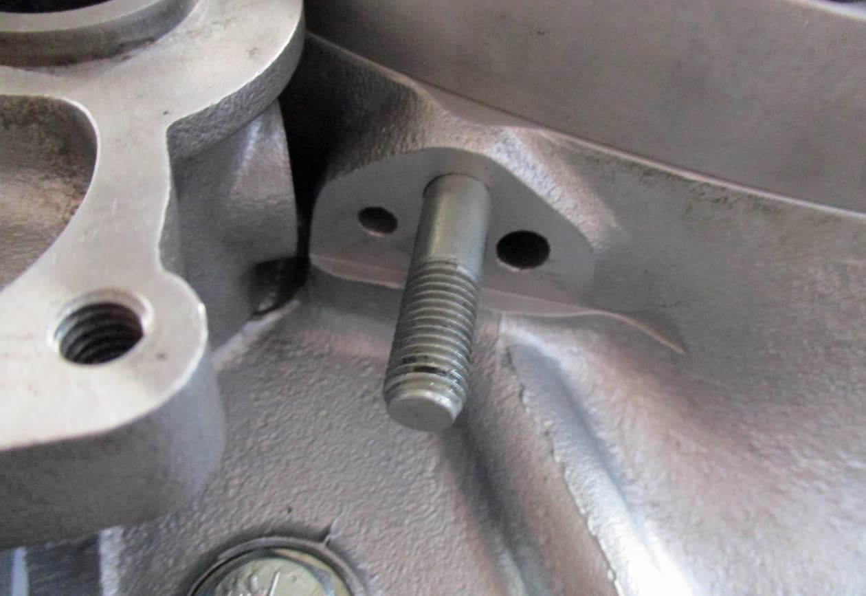
These are the old stator bolts. Lack of maintenance and/or no primary chain tensioning has caused the chain to rub into the bolts.

So, new ones (they needed the thread recutting so they screw in easily) with a dab of blue locktight are fitted.
The torque spec for these is too high and can strip the thread in the casings. Just do up tight as you would with any stud, no need to go mad.

Slip the rotor onto the crankshaft over the key. Sometimes these are tight but don’t hammer them on, they are magnetic and this can be affected if bashed. If they can’t be pushed on by hitting with your hand then use a sanding cylinder to take out some of the centre. It shouldn’t be loose but a tight fit.
A loose rotor will bang against the key as the primary chain takes up any slack and will cause damage to the slot in the crank shaft.

A new crank shaft stud, note which way round it goes. Short threaded section in towards the engine.

Then a new tab washer with the key into the slot.

And finally the nut with the shouldered section in towards the engine.

Torque the clutch centre nut to the required 70 footpounds and the crank nut to 40 footpounds as shown in the spec.
Bend the tab washer over on the crank.
Then check the primary chain tension.
Take the sparkplugs out so the engine can be turned over a few times giving the chain a few turns.
The spec for the primary chain is a slack of just under 10 mm.
Don’t get all confused over how to measure a chain slackness.
Lightly push the chain down and note where the bottom side of the chain is, then lightly push the chain up and note how far the bottom side of the chain moves to. This is the slackness, easy.
Tighten or loosen the tensioner as required, sorted…
Over… ![]()
9 Likes
Now to index the gearbox. Here’s the gearchange arrangement from the workshop manual:

Moving the gearchange pedal up or down moves the spindle and the quadrant to move the plunger quadrant (No 4 in the diagram) up or down.
This then moves the inner gears of the plunger quadrant causing the cam plate to turn. The slots in the cam plate then push the selector forks to move the gears along either the mainshaft or the layshaft in the gearbox.
The changing alignment of the gears then differs the ratio of the drive from the engine onto the front chain sprocket.
However, as the diagram shows there’s only a limited amount of teeth on the plunger quadrant. It is not a circular gear, it’s butterfly shaped.
The very bottom gear of the plunger quadrant is used for 1st gear and the very top gear of the plunger quadrant is used for 5th gear. So, the whole length of gears on the ‘wing’ of the plunger quadrant is needed to be used to give the whole range of gearchanges required.
So, it’s really important to set this quadrant in it’s correct aligning position to enable all gears to be selected.
This is called Indexing the gearbox…such fun

There are a few methods but this is the one I generally use. Take the outer and inner gearbox covers back off to expose the gears.
This gearbox is set in neutral. The driving dog gear (shaped like a cross) isn’t meshing with the layshaft first gear. The cam plate tab can be seen down by the plunger.
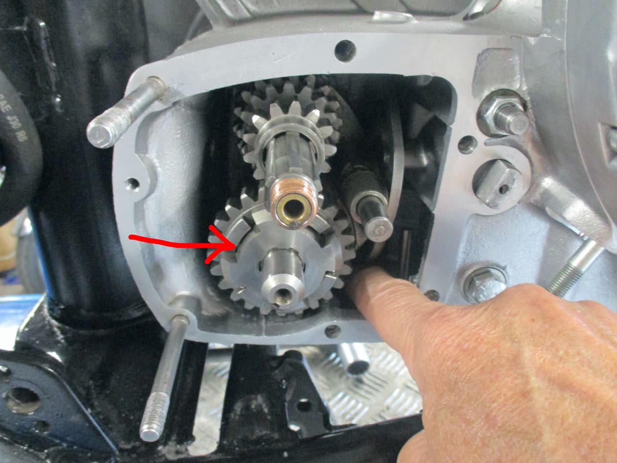
Move the cam plate into 1st gear by pressing on the camplate tab pushing it into the engine. The cam plate will turn and the plunger will slip into the 1st gear slot.
Make sure the driving dog is moved so that it meshes into the layshaft 1st gear.

This is the inner gearbox cover. The limited number of gear cogs can be seen on the plunger quadrant. Using a finger full of grease ‘stick’ the thrust washer onto the nipple until it’s all secured and bolted up.

If using some form of gasket seal only put it on the inner gearbox cover to stick the gasket to it. It’s very common that the gearbox will NOT be indexed correctly on the first try. Plan to take the inner gearbox cover off several times in the quest to get it right.
As a note, I can’t remember ever achieving the indexing on the first try. This one took me 5 goes (yes, I counted especially for you) and included a walk around the garden to look at the sky to calm me down.
It can be very frustrating, especially if you think you’ve done it and only find out later when riding on the maiden voyage that the gears don’t work correctly.

Push the inner cover onto the studs and mainshaft until the plunger quadrant stops any further progress. The plunger will jam. Pull the cover back off until theres about a 5mm gap between the cover and the cases.
The plunger will move freely up and down.

While holding the cover in place position the plunger so that the first tooth’s top edge (that’s the second gap’s bottom edge) aligns with the centre of the mainshaft and the centre of the gearchange spindle’s hole.
Push the inner cover home to maintain this position of the plunger.

Once pushed home use a straight edge to make sure the plunger is in the correct position. The top of the first tooth or the bottom of the second gap aligns with the centre of the mainshaft and the spindle hole.

There’s 3 different sized bolts that hold the inner cover in place. Tighten these up.

Assemble the kickstart ratchet keeping it all pressed together as it’s built - washer, then pinion sleeve, then spring, then pinion, then ratchet, then tab washer and finally the nut.
Tighten it up by locking up the clutch as previous. Don’t torque it to spec yet, the gearbox needs to be working correctly first.

Put the gearchange pedal on (I use this cut down hand gearchange so I can reach it from the other side of the bike)

Temporarily put on the outer gearbox cover complete with the kickstart (this allows the engine to be turned over to help the gears slot in). Remove the sparkplugs so the engine to turns over easily.
Now, change gears using the pedal. Move the kickstart as each gear is clicked in to see the chain sprocket turn. Take it through the gears up to fifth and back down to first. Make sure neutral can be found. Pull the kickstart and hold the chain sprocket to ensure neutral is working.
Then go through all the gears again.
Don’t be suprised that it moves through all the gears to 5th then it won’t move back. Or the gearlever jams, or it sticks in neutral, or it’ll only go into third and not 4th or 5th.
The indexing hasn’t worked. I’ve no idea why, it just doesn’t sometimes. The plunger secretly slips somehow into a place where it wont work.
It all needs to come apart again and start over. Hence why the kickstart nut wasn’t torqued up and why the inner gearbox cover gasket was only stuck on one side. Go back to GO but do NOT collect £200.
Do it all again being extra careful to get the positioning correct. Eventually it will work. Some people do it first time every time, I hardly ever get it right first time. Go have a lay down, go for a walk, it’ll work but not just yet while the Triumph gods are laughing at you.

At last it works. Run round a lot, jump up and down, do cartwheels around the garden. Take the outer cover off and lock everything up to torque the kickstart nut. Revel in your fantasticness…

And with great relief bend the tabs over on the washer.
Enjoy…welcome…over ![]()
7 Likes
I’m never going to do this, but I am really enjoying your expertise and attention to detail. A little CG125 I’m fixing up with my grandson is SO simple compared to what you are doing. Thank you for the education and entertainment.
2 Likes
Thanks @TallPaul - I think it’s taken longer to do the photos etc than actually to do the work so I’m glad gang members are enjoying it.
How great is that, doing something with the Grandson. I’m hoping others get to dig in their bag of spanners and have a go at their own project - alongside younger family members must be really nice. ![]()
4 Likes
Can close up the gearbox end of the engine now

Engine plate bolts on - I’ll use two of the bolts here as an earth to the negative side of the battery. It’s important to get a really good earth on the engine as this is required for the stator (electronic points). I don’t assume the earth through the frame anymore after blowing the ignition unit on a build a while ago.
Before putting on the outer gearbox cover it’s really worth doing the oil junction block that’s hidden underneath once the cover is on.

There’s a range of oil junction blocks through the years. This bike had the weird curly one on originally. But I’m gonna try the shorty straight one this time.

Make sure the small gasket doesn’t obstruct the feed or return holes. Sometimes they can be made incorrectly and have to be altered slightly to align with the oil holes. Bolt it up tight. I’ve never had a leak here so don’t go mad with the spanner.
Notice which way round it fits - it’ll only go on one way. The narrower tube is for the oil return flow back to the tank and to the rocker covers - and the wider tube for the delivery from the bottom of the oil tank. So, Front is the delivery and Rear is the return.

So, there’s two different bores of fuel/oil rubber pipe to suit. The wider one is 3/8 inch and the narrower one is 5/16 inch. The nearest available metric pipes are 8mm and 10mm which will be ok as they are sealed up with a jubilee clip but, if you search, you can get the more accurate 7.9mm and 9.5mm as above. (Bloody show off ![]() )
)

Connect the pipework up and fenagle the jubilee clips to allow easier access later on when they may have to come off again.
Don’t cut the pipes yet, just connect them.

Run the return pipe in the desired route to the connection junction in the top of the downtube, then cut and connect.
Note the continuing metal pipe to for the return to the rocker covers - I’ll do that small length when the rockers go on properly later on.

The larger diameter pipe is cut and connected to the feed off of the bottom of the frame. I’ve not put in a filter yet so I’ll just connect it up temporarily until I get one.

Select the appropriate gasket and sealer for the outer gearbox cover.

Wind the kickstart spring up by a couple of turns of the kickstart (make sure the spring is tight enough to miss and cover joins. The kickstart needs to be held at about 10 o’clock ish to allow the quadrant to go past the ratchet. Push the cover on and twiddle the gear pedal to allow the last few milimetres onto the gear spindle slot.

Bolt it all up and then fart around trying to get the brake and foot pedals in place. The back brake on these T140s was an add on to the older design and they are quite a puzzle. Getting the spring onto the return can be almost impossible without breaking skin so I try to get it all in with the spring already connected. You’ll see what I mean when you try to fit yours ![]()
…thankee…welcome…over…
9 Likes

New pushrods and rocker box gaskets.

The pushrods need to be positioned on the tops of the tappet cam followers. Easier if building the engine on a bench but in the bike it’s really quite diffcult to see them. I resorted to a mirror and a torch to check.

Put a blob of grease in the cup of the pushrod going down onto the tappet.

The grease helps as you can feel when the rod is on the top of the tappet as it sort of sticks there. Look to make sure they are located correctly.

Place the gasket on. The gasket has two holes to accomodate the pushrods. It holds them in the correct position to align with the rockers when putting the boxes on.

Blob some grease on the tops of the pushrods and tops of the valves.
Turn the engine over until both the puahrods are at their lowest level and undo the rocker adjuster pins and locknuts so they don’t put any pressure onto the valves as the rocker boxes are pushed on.

Threadle the rocker box on using the three studs on the front through the holes in the head as a guide. It will be almost touching the central head socket nut so is a bit of a squeeze but it should push on easily if it’s in the correct position.
Loosely screw in the rocker box studs to hold it onto the head and turn the engine over while watching the rockers. They should move up and down if the pushrods are in the correct position.

Screw on the three rocker box bottom nuts and washers and torque it all up to spec.

And repeat for the other rocker box.

Valve timing/tappets/rockers can now be adjusted as per the manual. 6 thou for exhaust side and 8 thou for inlet.
Put the cover gaskets and covers on. Done. Luvly.

Couldn’t help dangling the TT zorsts on and standing back wiv a brew. ![]()
9 Likes
Such a cool looking bike
3 Likes
Very Fonzy
4 Likes