T140e 1980

Was up early this morning for the daily walk, was quite pretty

Had to move the bikes around as some other one has been hogging the lift. Looking stumpy out in the morning sunshine :no_mouth:

New kickstart spring arrived so off with the outer gearbox cover again. I only put the kickstart cotter pin in when it’s all up and running, in the mean time I just use a nut and bolt.

The new and old, the old one was tired, a bit rusty and needed an extra wind to return the kickstart properly.

A bit of a fiddle to get the new one on the shaft, making sure it’s in the correct location as per manual.

Wind the kickstart up a couple of turns to tighten the spring

And whack the cover back on. Still using the nut and bolt for the kickstart as anything could happen in the next half hour… :slightly_smiling_face:

11 Likes

1st kick must be on the way soon!?
Definitely a video for that please!

5 Likes

I’ll film it, but don’t know where I’ll show it. It could be soon or never if it’s up to Royal Mail :neutral_face:

Some bolts came, hooray! Nope, the threads are rolled so they need to be recut to allow them to actually screw in :no_mouth:

3 phase (as required on later T140s) better charging at lower RPM apparently, although I don’t really know about electrickery things. Correct Lucas Number as per parts catalogue.
3 wires so go for a three yellowed wire Rectifier/Regulator as well (still waiting for that).

Fiddle the stator on over the rotor. Heavy magnetism makes it difficult to get the stator onto the bolts squarely but it waggles on eventually.
There needs to be some air between the rotor and the stator all the way round. Turn the engine over and try with a feeler gauge to make sure it’s all on square.
If there’s a tight spot the stator can be eased over by tapping on the long bolts in the direction the stator needs to go. Remember to take everything off if trying this as neither the stator or the magnetic rotor will thank you for clobbering them.

The wires have to go through a rubber grommet boot before going through the access hole. These are difficult to get over a two wire stator, even harder with a three wire…

…so use some circlip pliers to stretch the boot a bit. Not too much or it’ll rip.

There’s a little grommet plug for the outside too. Same, use the circlip pliers.

Long sockets are needed to do up the stator bolts. Even with the long reaching sockets sometimes the resin moulding on the stator doesn’t allow the parts catalogue’s locking nuts to either fit or do up tight as the moulding gets smaller closer to the metal body on the stator.

The long socket can be ground down to fit the moulding, the narrower barrel nuts will fit (as above), or use a normal nut with a lock washer so the socket doesn’t have to reach that last millimetre to do up. An extra washer or two could be enough.
I’d better get on with the 'lecktricks…over :slightly_smiling_face:

11 Likes

All sorts of weenie jobs need doing rather than start on the 'lecktricks…

Engine stay. Replaced the studs in the rocker boxes with bolts as they make the installation a bit easier.

New rocker oil feed is a bit narrow to take the standard oil pipework so push on a smaller diameter plastic tube first. Then the oil feed pipe will be all snug as a bug.

Oil feed to the rockers on. Note that I’m all out of the correct size dome nuts so I’ve screwed on some old rusty nuts to remind me to order some.

At last, need to do this. These are the three wires coming out of the ignition switch seen in the background.
Wire B is from the battery. One click on the ignition key joins wire B to wire IGN. Second click on the ignition key joins wire B and wire IGN and wire ACC…
I tested it by joining the B wire to the positive on a battery. Then attached a tester (bulb, tongue, whatever you have to hand) to wire IGN and on to the negative on the battery then turned the key. Did the same with the ACC wire then labelled them before I forgot.

…so the positions shown on the wiring diagram all join as the key is turned. Just in case no one was paying attention. Easy peasy. Yea right.
Onwards and cut and solder and cut and thread and solder…ho hum, this takes ages but you get the idea just join up the wires as shown above. :neutral_face:

7 Likes

Couple of bits that could be helpful

These wiring joiny things are quite handy. I solder the wires together then slip one of these over the joint and they shrink using a hot air gun. The circle of solder in the tube also melts onto the joint as it’s low temp stuff. I also shrink wrap the joint over the top.

Weenie lights for the people who like lots of warnings. They are cheap as chips and work quite well.


Drill a suitable sized hole, screw in the casing and stick in the bulb. I dab on some glue too just to make sure it doesn’t rattle loose.

Shrink wrap the wires and connect up to your favourite warning mode. This is for the oil pressure, I’ve mounted this one on the side of the headlight so I can see it passed the centrally mounted speedo.
I like to keep the wiring in the headlight to a minimum.

Quite bright enough to see in daylight. They come in all colours too…over…

9 Likes

That’s the headlight I bought for the Suzuki and for that reason too, I still have the little LEDs, I have a gear indicator, since the GS had one as standard and need to work out the wire to wire combination, haven’t fitted em yet, I’ve also got a remote control (fob) battery isolator I was going to fit as an extra security, nice Chinese unit, cheap and looks just like a car key fob, loads of room to fit. I should get it done.

3 Likes

Yeah, I was thinking about fitting a security switch so I ordered some on/off toggles. I now have a bag of them but haven’t decided where to mount one. (it would also substitute for a kill switch just in case a carb slide jams - although letting the clutch out sorts that)
I should get it done as well :stuck_out_tongue:

1 Like

So, got that done

Bag of toggle switches

They come with screw on rubber covers if required

And, in place. I should be able to switch while sat on the seat all secretively like. Yes…we’ll see… :thinking:

6 Likes

Just in case you were worrying…

…the electrickery has been slowly installing.

8 Likes

My least favourite job… And yet it makes so much difference to the looks when it’s neat and tidy with clean lines. What wrap do you use?

1 Like

Takes me ages to try to get it looking right and is also my least favourite bit.

This is the stuff I use. I like the cable tidy stuff (whatever it’s called) as it covers nicely, allows the wiring to bend easily and can be removed/replaced. Lots of shrink sizes and the minimum of tape.
I’ve moved away from connectors of any sort - even the pricey bullet ones. I hard wire almost everything other than back light, alternator and points stator connections.

Wiring is now complete - hooray…battery inserted and everything works. Such a relief when the hooter makes a noise :slightly_smiling_face:

Sat looking at it outside while I did a ‘bits to complete’ list. It’s a lot longer than I thought it would be…over…

11 Likes

Cooler than a shaved polar bear in an ice bath :heart_eyes:

2 Likes

Think I’m sporting a woody…

2 Likes

Thanks gang members :slightly_smiling_face:

Right, fitting an electronic speedo. Some bikes I leave the existing speedos and rev counters on and some I put one of these on. This one left me with no choice as the existing dials have gone and I like these speedos, small, clean, not too expensive, no idiot lights, etc…

I make up a stainless bracket, rather than the one supplied. Important to leave the buttons on the back exposed as access is required to set it up and if tracking mileage on trips.
The wiring is pretty easy, there’s a constant power from the battery (I suppose that’s to keep the mileage to date memory going but remember that’s a drain on the battery) a power connection from the ignition and an earth. The sensor lead just plugs in.

One of these, with a fitting bracket, comes with the speedo. It’s a sensor that picks up when a magnet passes it.
Basically, the speedo calculates the bike’s speed from the time taken for the magnet to travel round one complete circle.

This is the bracket supplied with the speedo. I bolt it into the unused mudguard mount on the fork ends.

Adjust the sensor position with the little grommet bolt in the bracket. In this position the sensor aligns with the wheel bolts.

These are the little magnets supplied with the speedo and have to be positioned on the wheel so the sensor can sense them passing.

I mount the magnets in the wheel bolts. There are 4 wheel bolts but I only mount 2 magnets. The instructions say the more magnets mounted the more accurate the speedo reads but I’ve got other bikes with only two magnets and the speedos work fine.
I drill the bolt head to take the magnet.

I leave the magnet protuding slightly. The magnets have to face a certain way to the sensor - I just check against another bike in the garage by holding the magnet to be positioned up against an existing to get the N and S side. The magnets stay in ok just with their own magnetism, no need to glue them in. I’ve never lost one.

Stick the bolt complete with magnet back in the wheel. Then drill and put a magnet in the opposite side bolt - there should be an equal space between the magnets as the speedo will use the spacings to claculate the speed (it will assume the gaps are equal when it’s told how many magnets there are - there can be an odd or even number of magnets as long as the gaps are the same)

Adjust the sensor to be as close to the magnets as possible - I think they need to be withjin 8mm or something like that.

Then the wheel’s circumference is required so the speedo knows haw far you’ve travelled on each pulse from the magnets. So mark the tyre and the floor.

Push the bike until the floor can be marked once the wheel has completed one full turn.

Push the bike back to the first mark (just to check) and measure the distance. This is the circumference of the wheel. Obviously, different tyres, wheels, pressures etc will make a slight difference so amend if and when things change.

Write this important information down so it’s not forgotten. I’ll keep these details in the bike’s folder along with the speedo’s instructions for the next owner.

Connect up a battery (they’ll be a new one once the bike is running). I also install an optimate connector to allow easy charging in the future.

Using the adjustment buttons tell the speedo the circumference of the wheel and how many sensors there are. Job done. No point in spinning the front wheel as the speedo needle will only flicker. I’ll have to wait until it’s running and it has brakes. :slightly_smiling_face:
Thankee…welcome…over

10 Likes

Stuff has arrived…

On with the clutch first. The thinner 7 plate (rather than the standard 6 plates) Hyde clutch. If adjusted correctly they give a lighter clutch pull, easier neutral, no slip and no drag. Just nice.

Make sure the clutch rod is in place before starting (it can be seen poking through the centre of the main shaft). I wipe the plates with engine oil rather than leaving them overnight immersed in oil. There’s no need, these work fine assembled dry but I wipe them over first. Friction plate in first…

…followed by a plain steel plate. These are new plain plates but if the old ones look ok give them a clean and make sure they are flat. Lay each one on a sheet of glass or a mirror to make sure they don’t rock.

Alternate until all 7 friction plates and 7 plain plates are in.

I also order a new ally pressure plate whenever I’m doing a clutch as they don’t warp. I’ve got quite a pile of the old types that’ll be going to the autojumble with me next time.

New spring cups go into the plate making sure the tab goes into the slot.

It simply pushes on while feeding the spring bolts through the cups.

The 7 plate clutch allows the use of T120 clutch springs rather than the heavier T140 springs. This also gives a lighter pull to the clutch lever.
After a few hundred miles the clutch may need to be adjusted as it will sometimes start to slip in top gear when the throttle is opened right up. If the cable adjustment can’t sort it then the primary cover will have to come off to tighten up the nuts on the pressure plate. I do this as a matter of course anyway when re-torquing the head as required when running in. I like to ensure the pressure plate is running true.

Bung the three new springs in (if using old springs make sure they are all the same length) and new spring nuts. I’m using the brass ones but cheaper steel ones are available. The brass ones don’t seem to get hung up on the springs ends so much when adjusting or when removing.

Tighten the nuts up until the bolts are about one thread into the slot. Leaving loads of adjustment if necessary (the tighter the springs the less likely a slipping clutch but the lever pull will be slightly heavier).

Insert the central adjustment stud and nut. This is what the clutch rod presses onto when pulling the clutch that then opens up the clutch plates. Adjust the stud so that it just touches the clutch rod, then back it off a quarter of a turn, then finger tighten the lock nut.

Sit on the bike and pull the clutch to watch the pressure plate move outwards to leave a gap between it and the first plain steel plate. Lovely. Now to adjust the cable correctly.
It’s really quire simple to adjust the clutch cable but some get a bit confused trying to get the adjustment correct.
As a note - sometimes when pulling the clutch lever on these and other vintage bikes, a clicking can be heard from the gearbox side of the engine. The clicking is being made by the ball bearings in the clutch raising lever assembly coming out of their recesses. This is due to the cable pulling the lever assembly too far. Adjust the cable correctly and the clicking will stop.

First fully slacken off the adjustment at the clutch lever.

Then fully slacken off at the adjustment at the gearbox end of the cable by fully screwing the abutment all the way in.

Then adjust the stud and lock nut in the clutch centre again. Loosen off the lock nut and screw the stud in until it just touches the clutch rod, then turn it back out by a quarter to half a turn.
Then readjust the cable ends to give the required slack in the cable, There needs to be 3 or 4 mm of movement (slack) of the clutch lever before it starts to operate the clutch.

Take out the sparkplugs to allow the engine to turn over easily and operate the kickstart to turn the primary.
While kicking the engine over operate the clutch and watch the gap between the pressure plate and the first steel plain plate. The gap needs to be as level as possible when the clutch is operated, If the pessure plate is wobbling then turn the brass screws in or out to get the plate as level as possible when the engine is turning over and while pulling the clutch lever. No need to get over excited and measuring it, doing it by eye is fine. It’ll get re-adjusted during the running in period.
Once happy and all is turning level then that’s the clutch done. Lovely…well done…over :grin:

11 Likes

Master class that man :slightly_smiling_face:

3 Likes

Cheers Steve :slightly_smiling_face:

Rebuilding the calipers. New pistons as the old ones were a bit pitted and i didn’t want to risk a leak. New seals, nipples etc :slightly_smiling_face:

Check the manual to remind oneself which way round the seals go. Ah, yes, of course, I knew that

Two sorts of seal, a square one and a ribbed one. The ribbed one sits just under the dust cover.

Make sure everything is clean, including the threads for the banjo and the bleed nipple as rust can build up in there.
Wipe some brake fluid into the grooves and onto the seals. Slip the bottom seal into the groove.

Like that. Then the dust cover goes on before the dust ribbed seal goes in. Otherwise the dust cover is even harder to get in.

As the metal dust cover is a really tight fit it can’t be pressed in even with super strong fingers. If using a hammer or trying to press it in with the vice it will bend and deform and be completely bolloxed.
There’s no ordering just a new dust cover, the whole set will have to be bought again.
So, to make sure there’s a bit of a lead in, I bend the leading edge in slightly with a pair of pliers. I go all the way round and check by holding it into the piston hole.

I hold about 2/3rds of the circumference of the cover in place and tap (and I mean tap) the remaining 1/3rd into place. I watch as I tap to make sure it’s not getting held up and getting distorted. It will, slowly, go into place.
If it’s tapped down too far, it can be levered up slightly with a flat bladed screwdriver so it’s level with the top of the caliper.

Then pop the ribbed dust seal in.

A bit of a fiddle but done.

Lubricate the piston with some brake fluid and it should just push in. It won’t if it’s not square.

Now do the other side

Just like that.

Put in the little seal for the line feed from one side of the caliper to the other and make sure the caliper is bolted together so the holes match up.

Run some locktight into the threads as these really need to stay done up.

Whack in a new bleed nipple and thread in a new banjo bolt. The existing banjos wont work as I’m going to be using Venhill’s brake lines (when they arrive pffft.)

Slip in the new pads and split pins.
And mount both the rebuilt calipers. On these Triumphs the front wheel has to be removed and the spindle dropped out of the rear to get them on, well it can be done with the wheels in but it’s a lot easier just to drop the wheels off.

“Well that wiring looks a bit shit” - blimey calm down, the speedo sender wire is just temporarily cable tied to the slider until the brake line is fitted - “oh ok” :smile:

Lovely…welcome :upside_down_face:

11 Likes

Ignition timing, innit :neutral_face:…with an old Boyer Branston pickle ignition system.
I’ve had one of the Boyer systems hanging around in the stash since about 3 builds ago. It must have come off a running bike otherwise I would have binned it so thought I’d use it on this build…

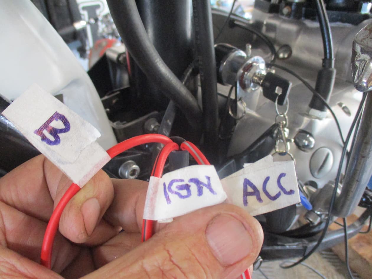
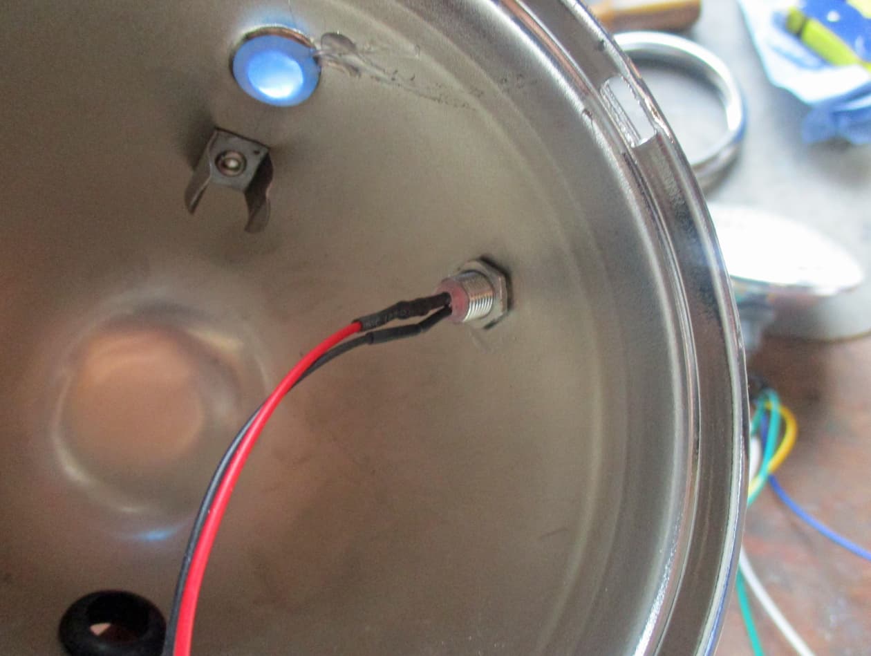
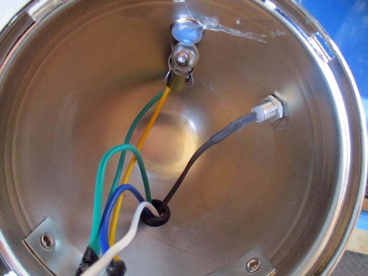
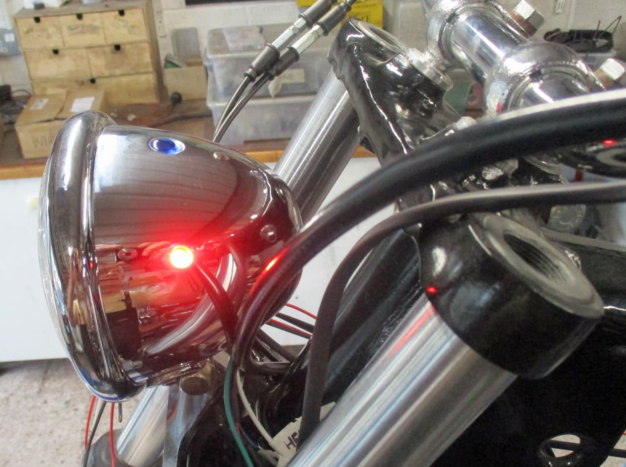
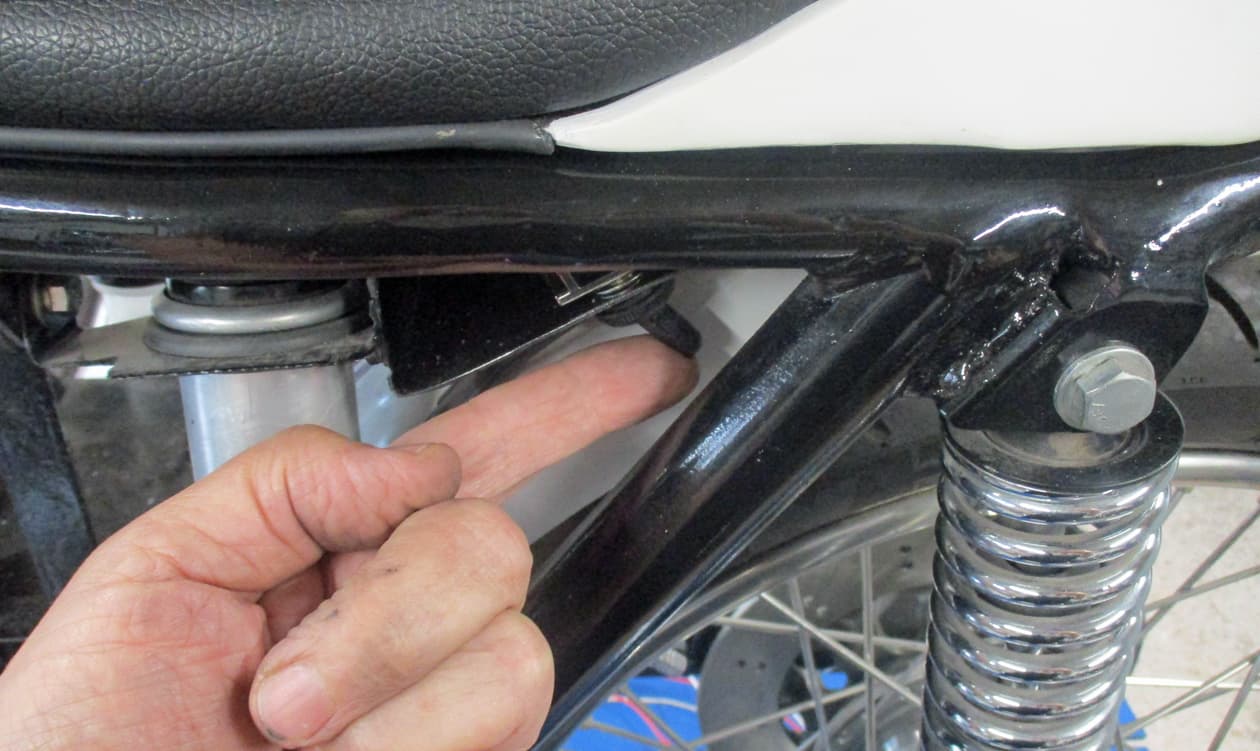
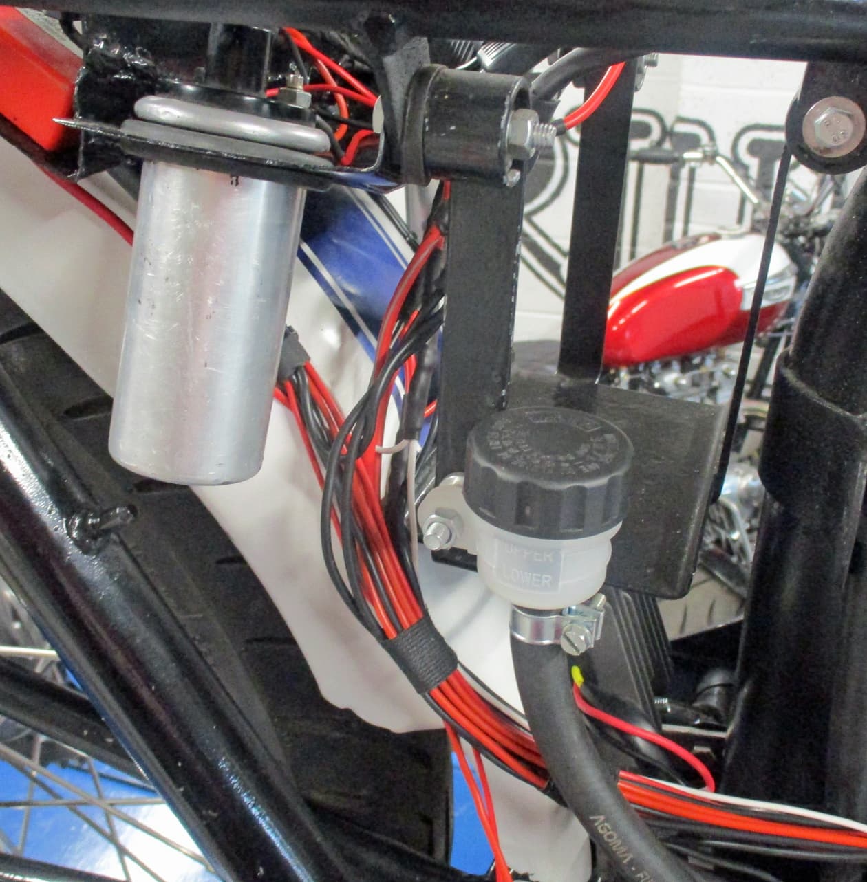
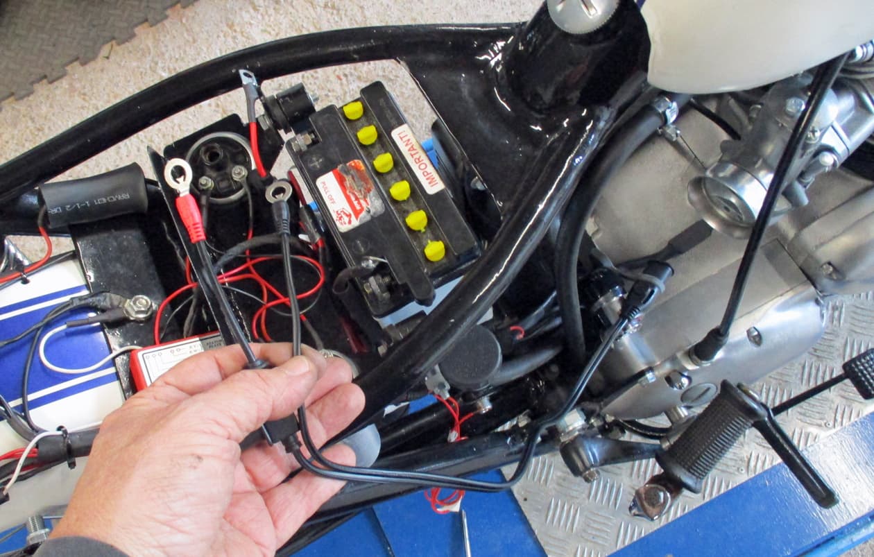
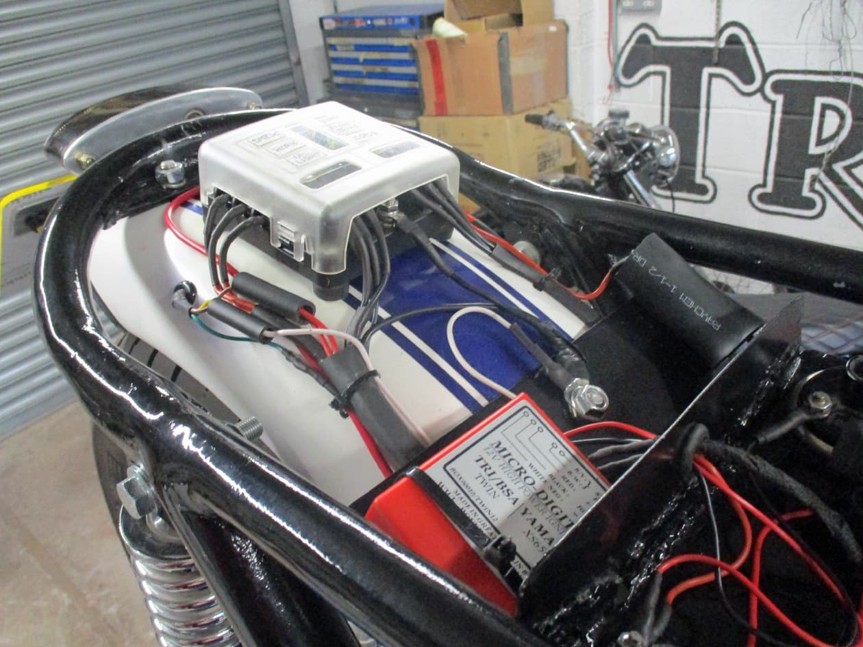
There it is - the red box - under the seat unit all wired in. Pretty simple to wire in:
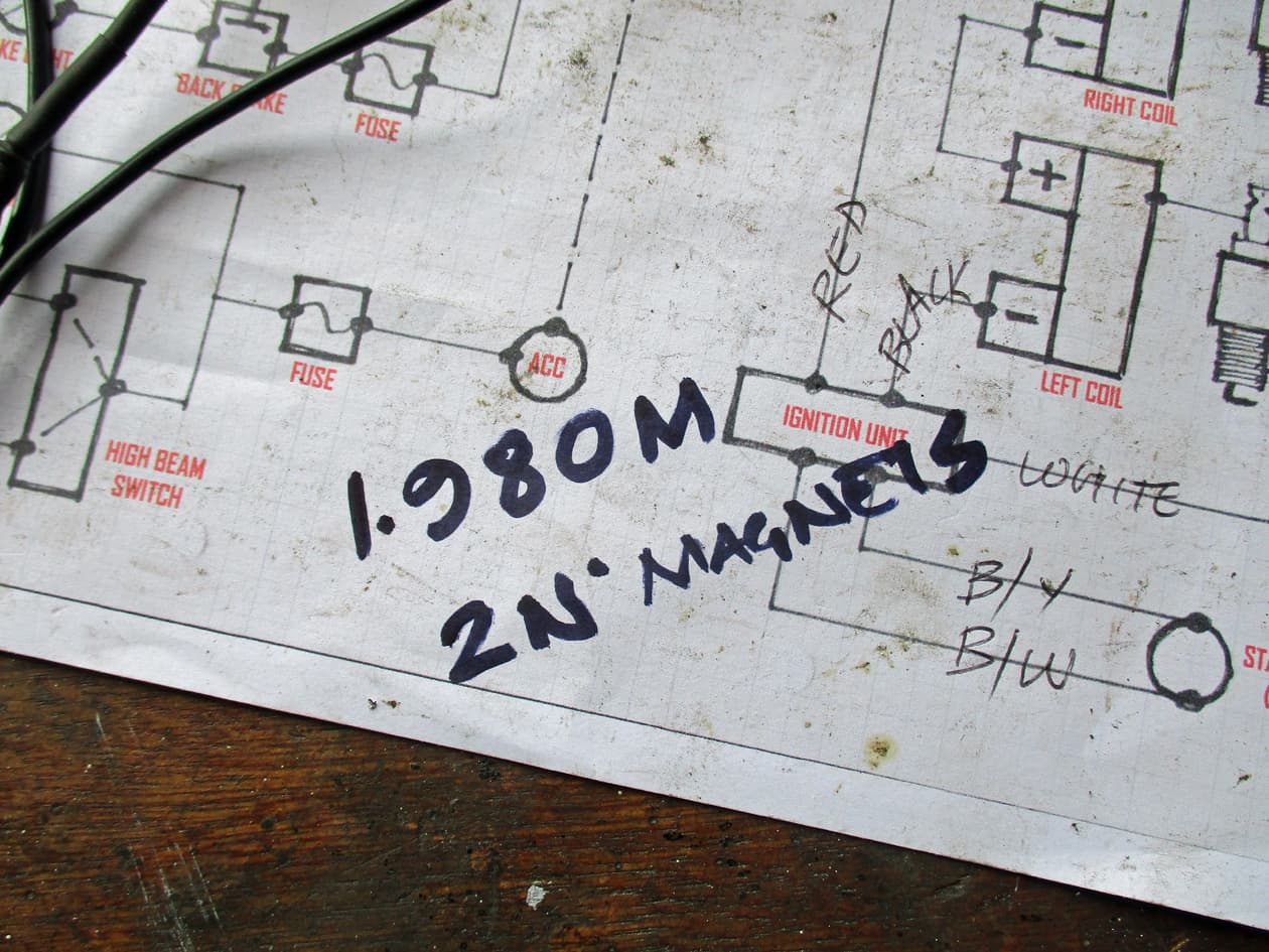
White wire is Earth, Red wire to positive side of right coil, Black wire to negative side of left coil and the other two wires off to the stator plate (where the points used to be).

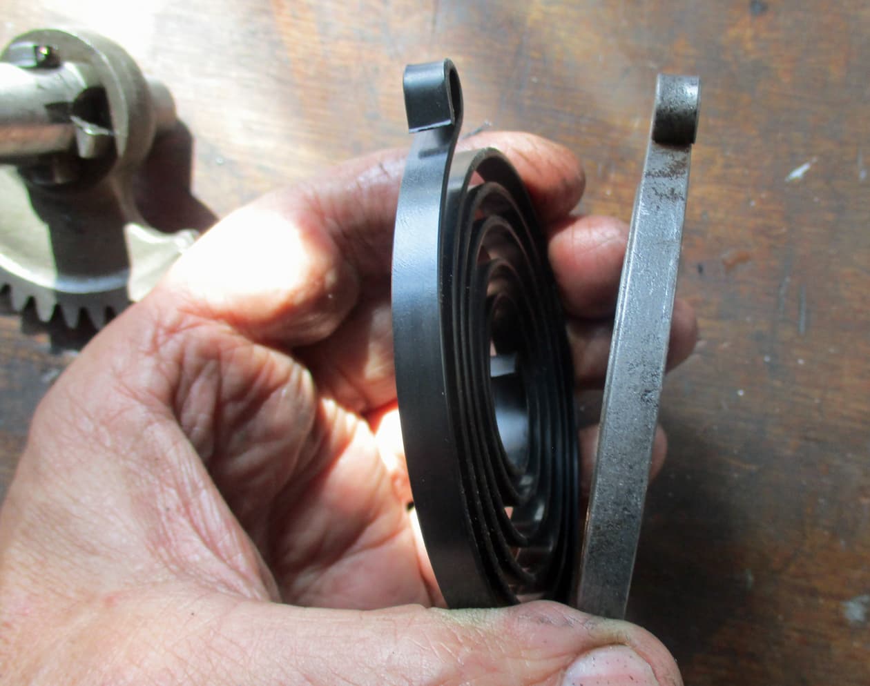
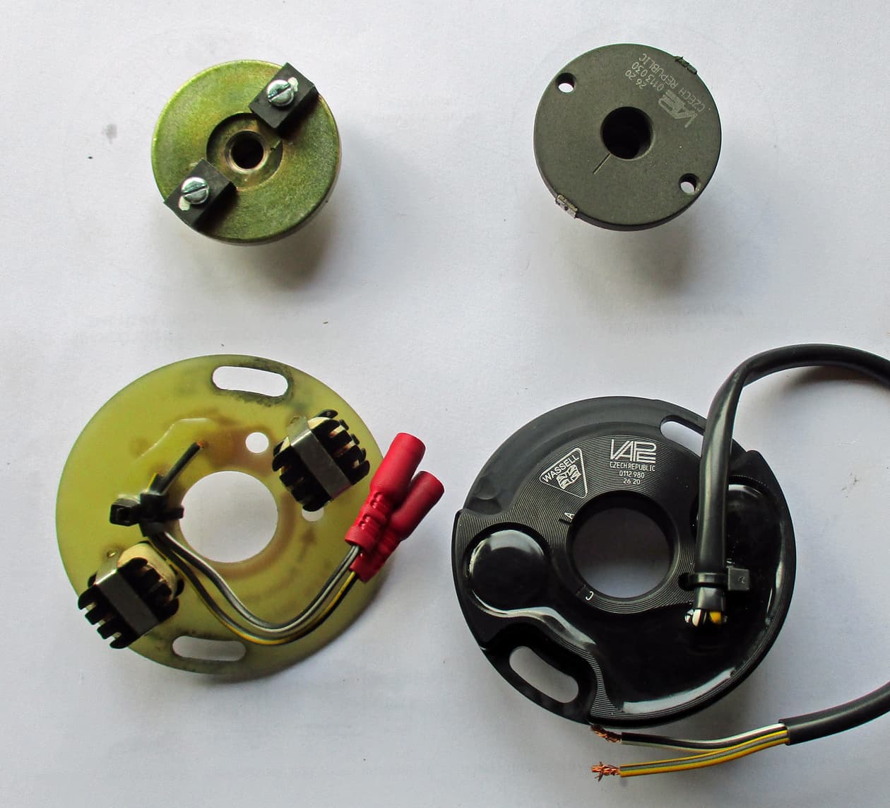
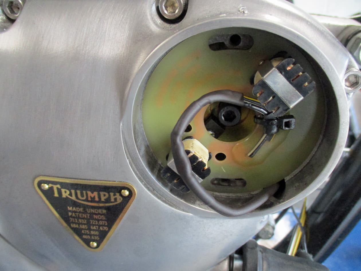
The Boyer/Branston stator plate is on the left. In comparison to the Wassell Vape system I usually use on builds.
The Vape system is one that I’d blown the ignition unit on a previous build by not earthing the engine (took me ages to work that one out) but the stator is fine as a spare.

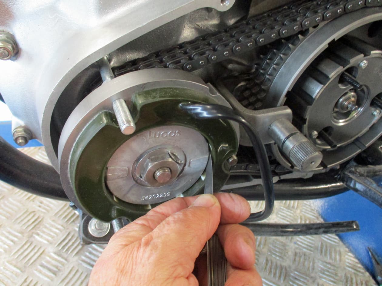
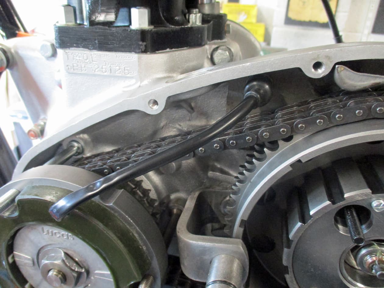
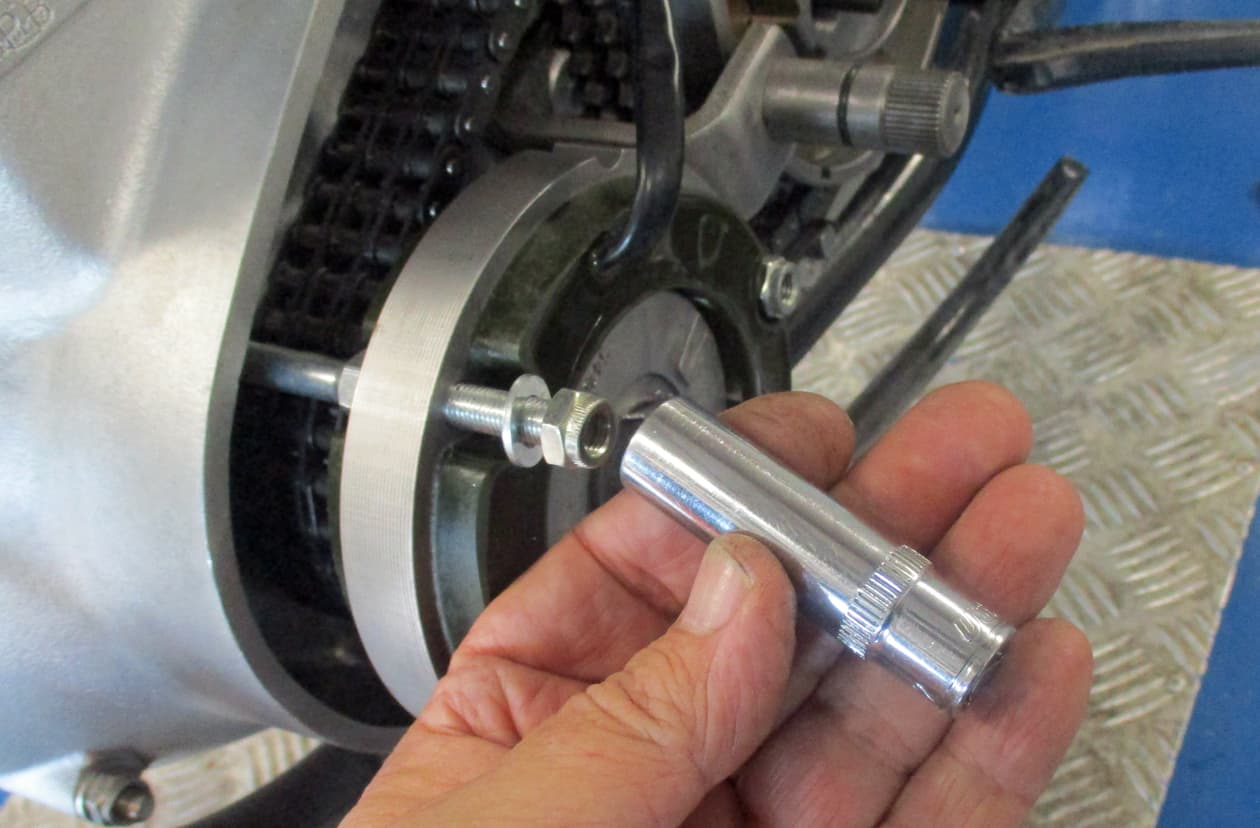
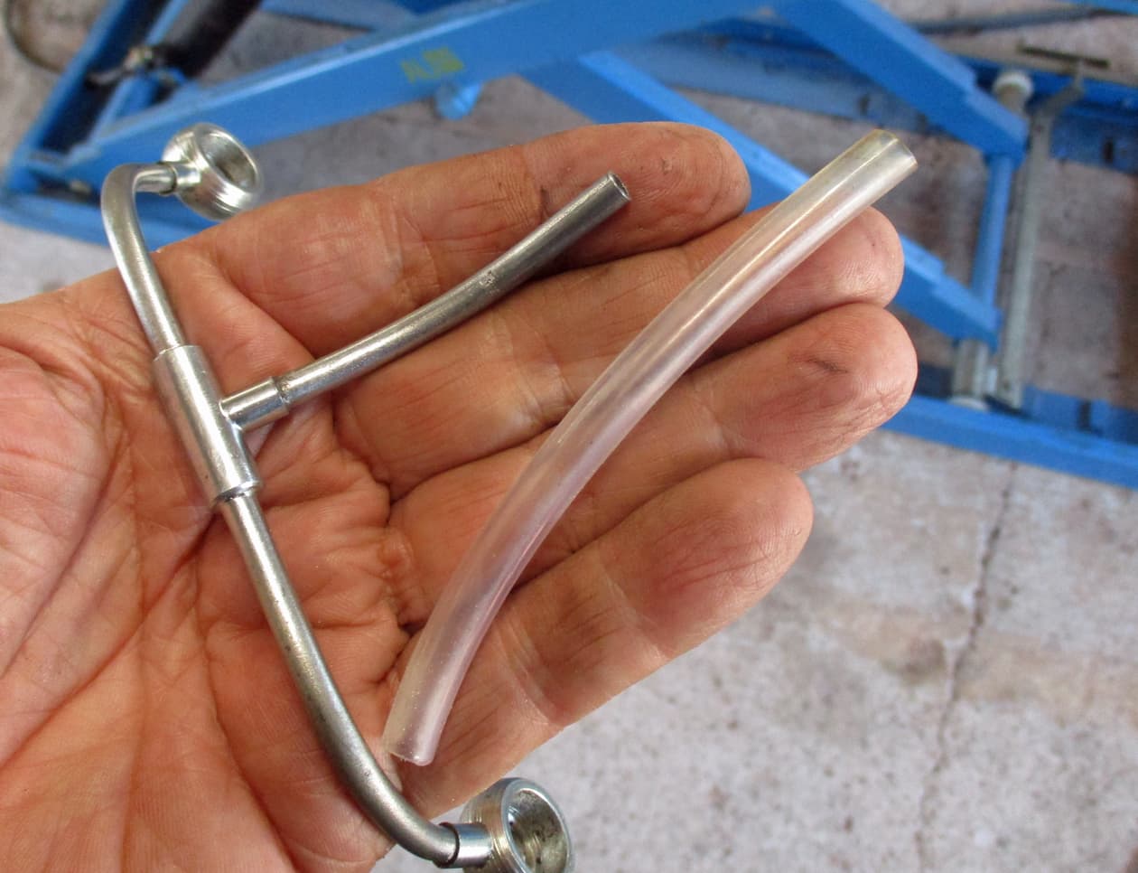
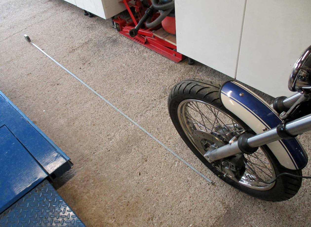
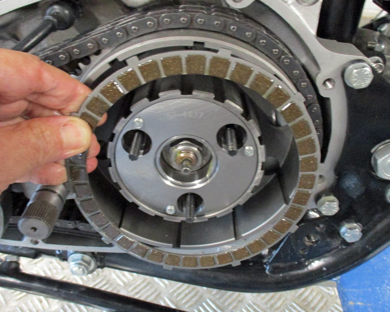
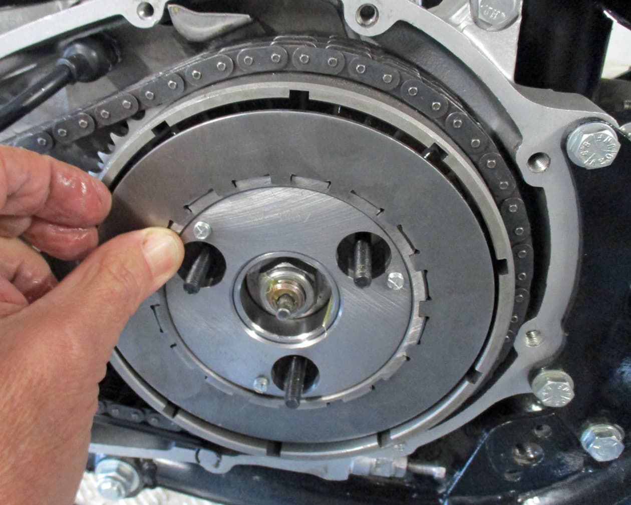
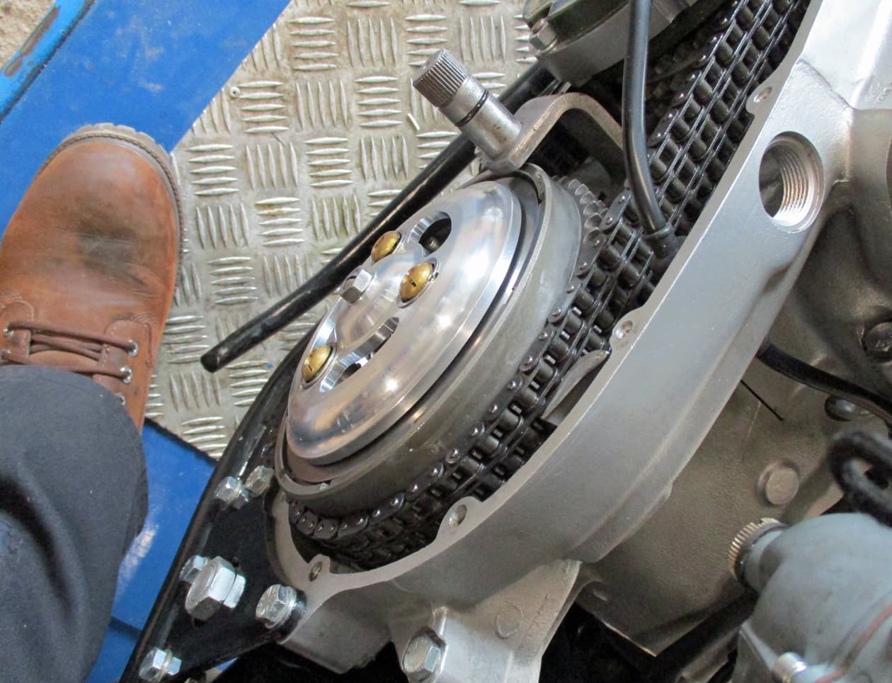
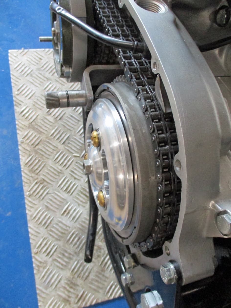
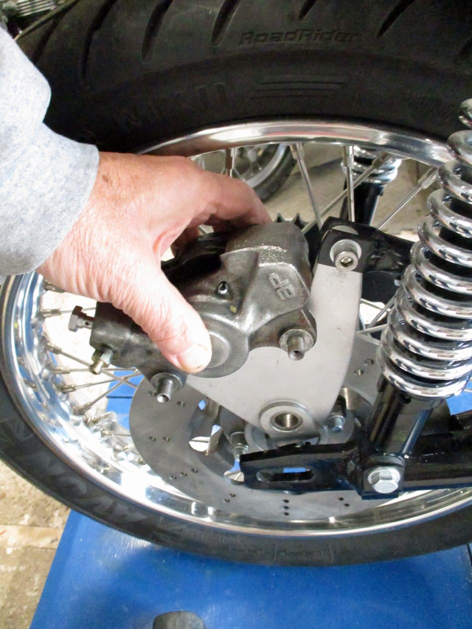
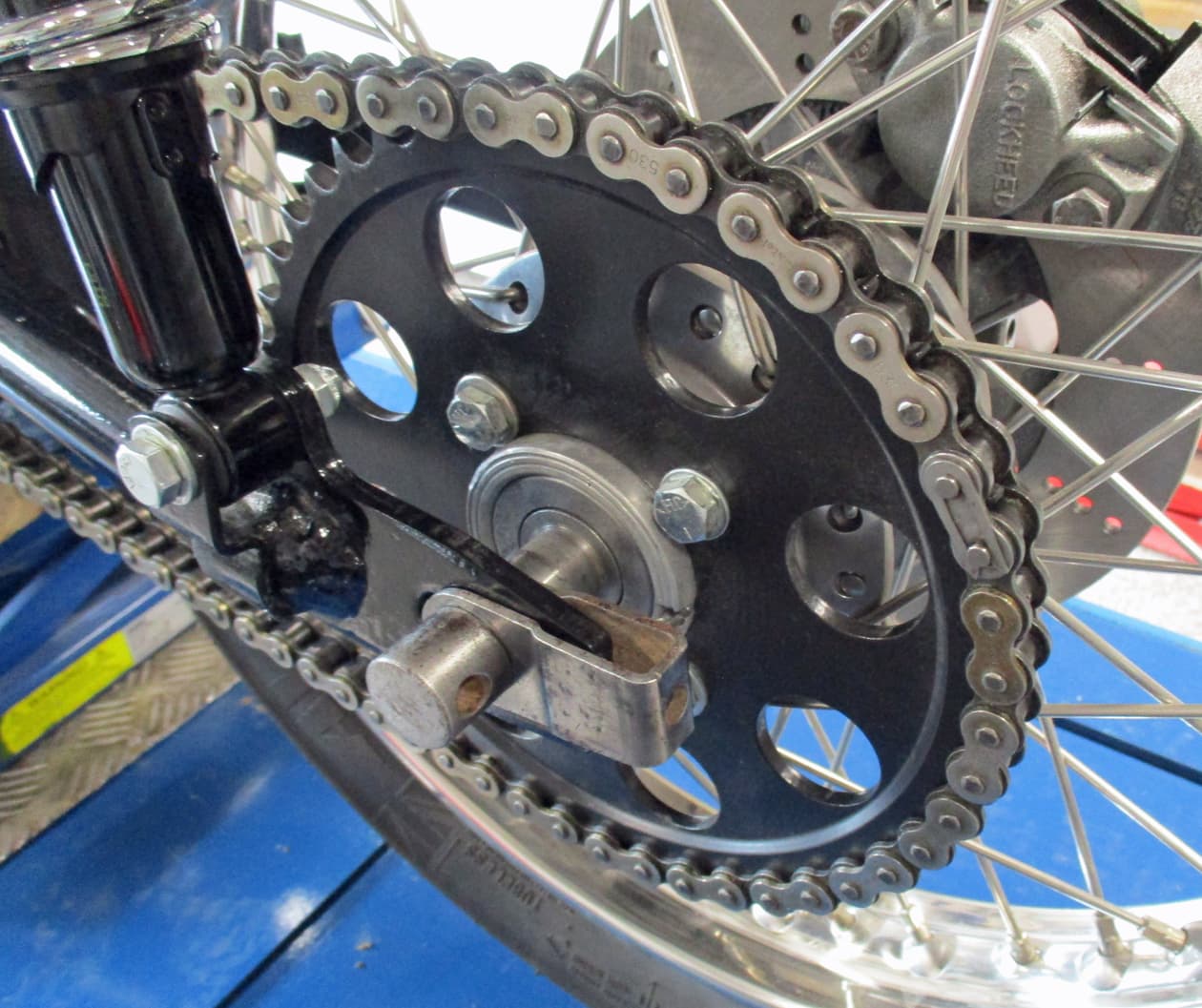
To help with the timing throw an old chain on so the back wheel can be used to turn the engine over - saves trying to do that with the kickstart or a spanner on the crank.
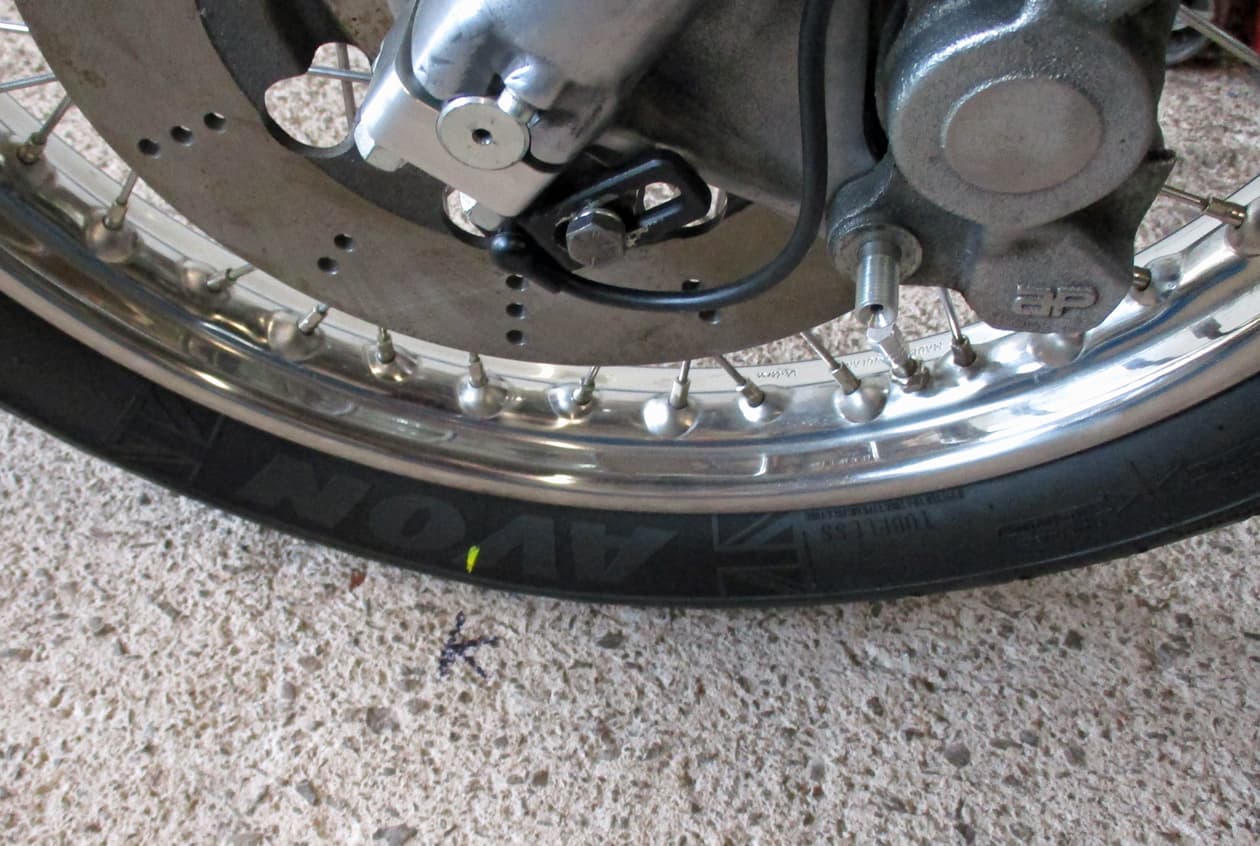
Raise the back wheel off the floor using a jack or a very strong wife so the wheel can can be turned by hand.

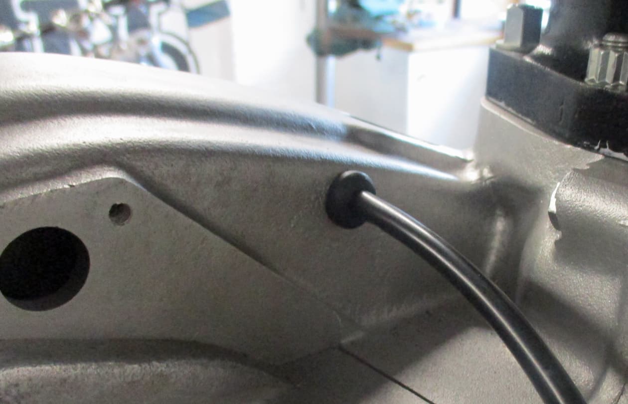
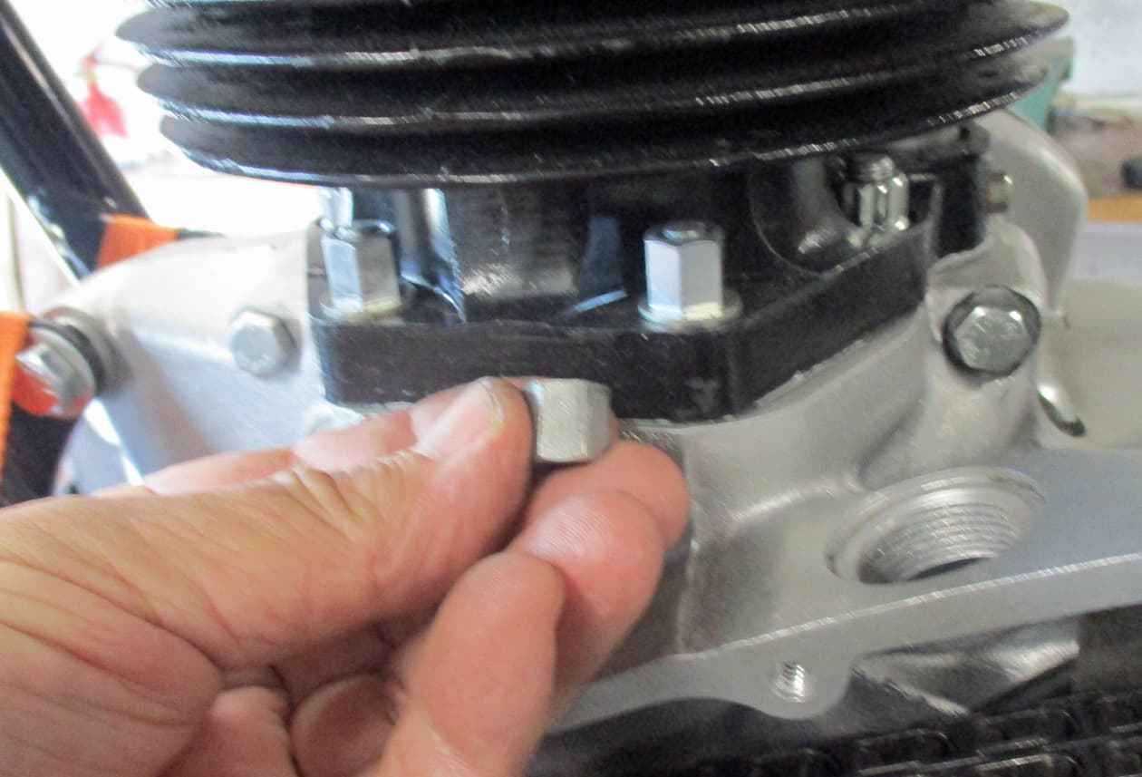
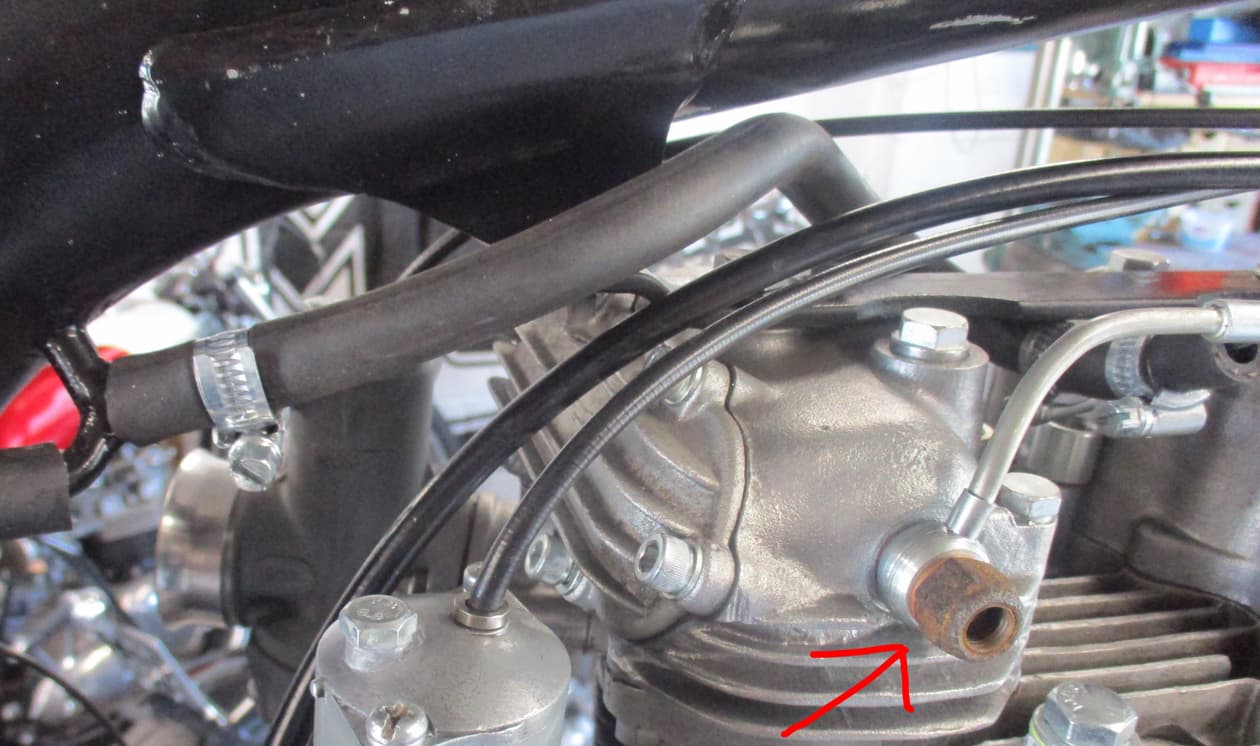
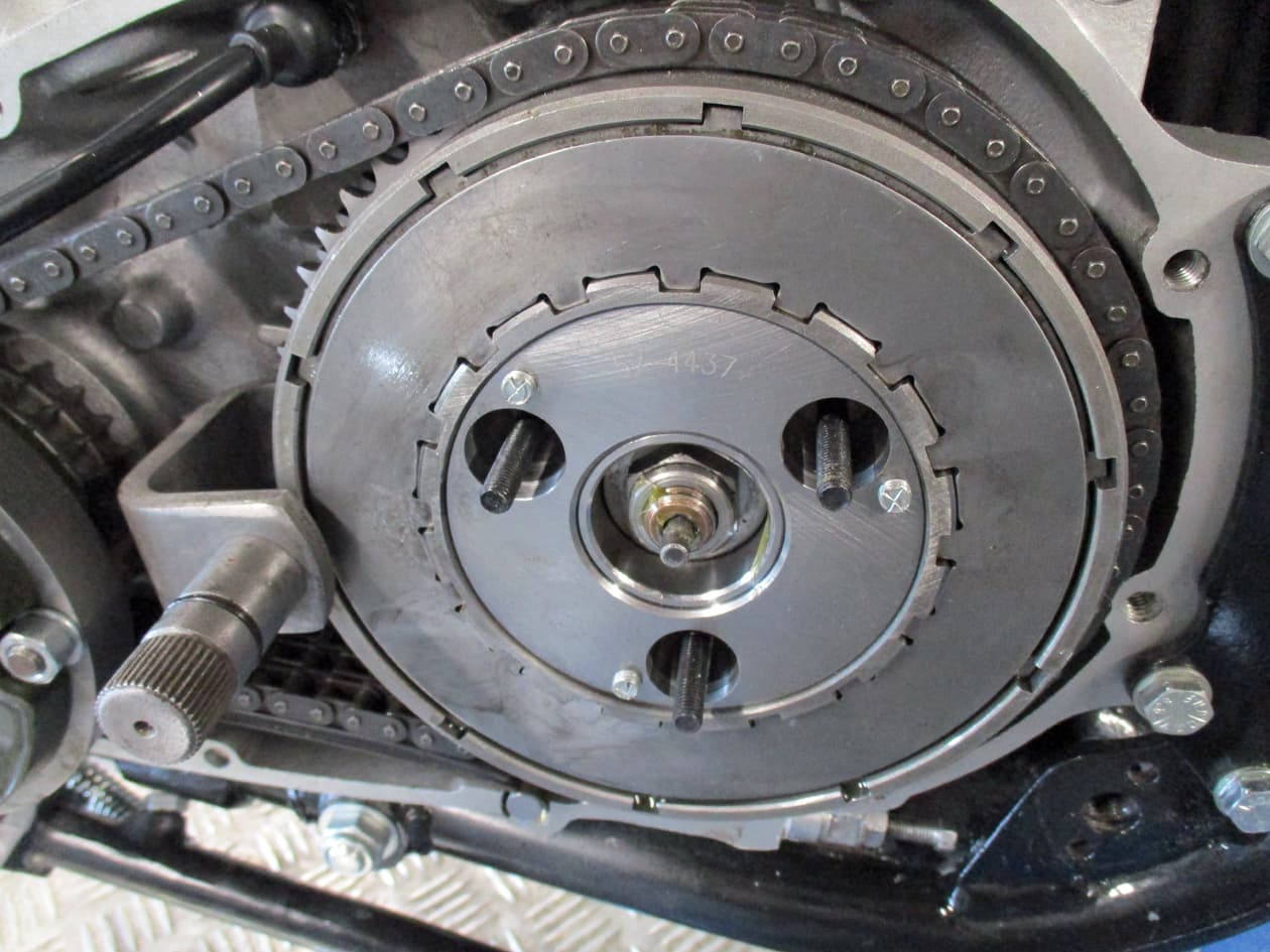
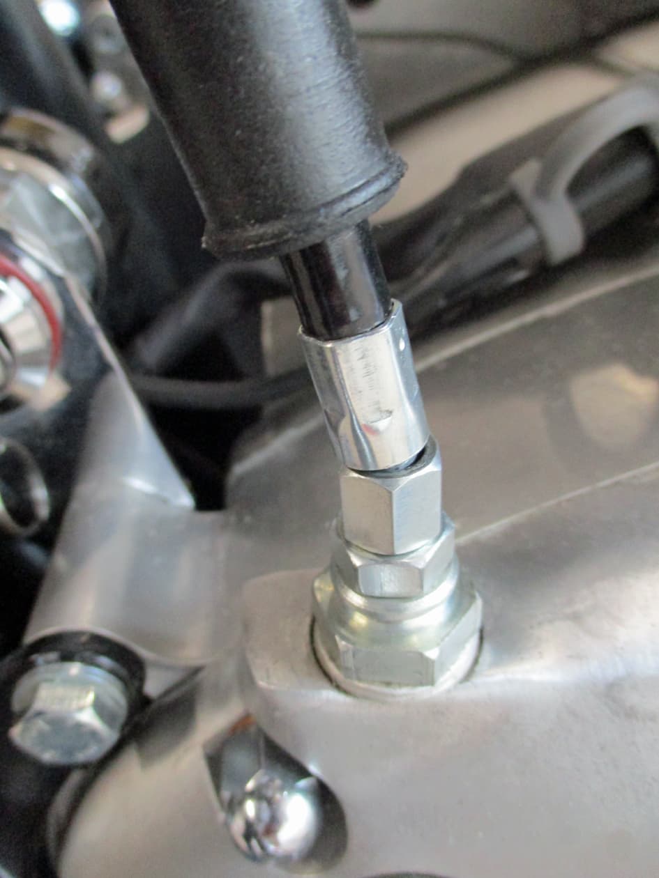
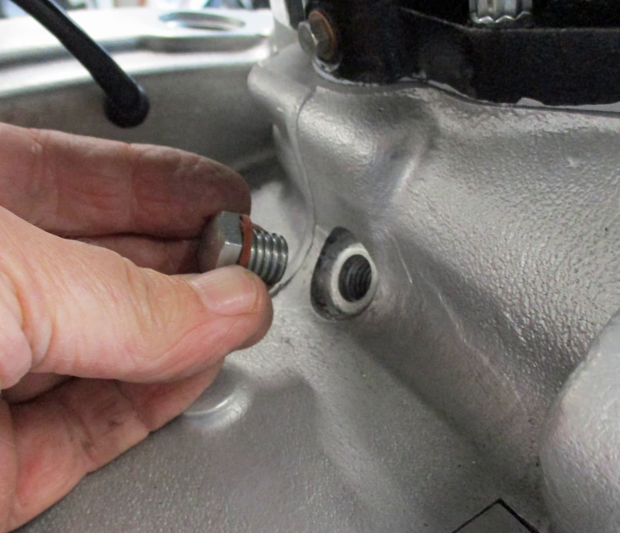
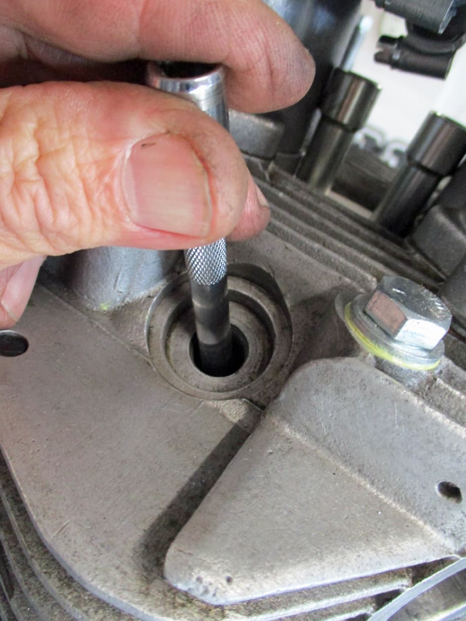
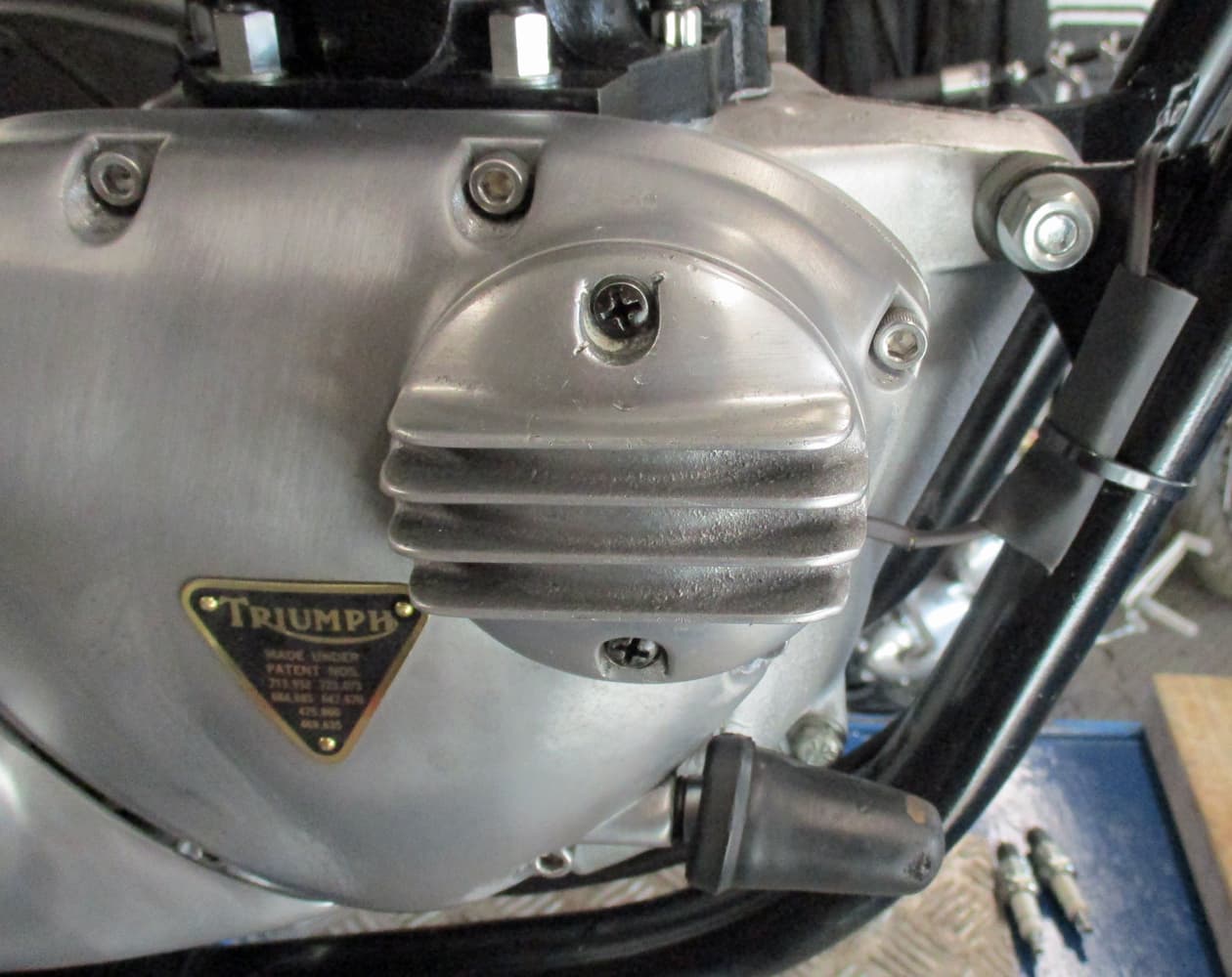
Take the timing access plug out of the crankcase just behind the barrels. This gives access to the crankshaft flywheel. The flywheel has two slots built into it which can be found through this access.
The slots will be directly under this hole when at Top Dead Centre and at 38 degrees Before Top Dead Centre.

Right, another small explanation - sorry Grannies and Eggs.
The fuel/air mixture is sucked into the combustion chamber through the carburettor by the piston moving downwards and the inlet valve opening.
This mixture is then compressed by the piston moving upwards and then ignited by the sparkplug. It’s therefore quite important that the plug sparks at just the right moment to get the best performance from the engine.
However, a fuel/air mixture does not combust instantaneously. It actually burns relatively slowly.
For an engine to be efficient, as much of the inflammable mixture should be burned as is possible.
The sparkplug causes the flammable gas to start to burn, it burns in a sort of ouwardly expanding wave, starting at the spark and moving across the combustion chamber in all directions.
It takes time for the majority of the burning expanding gas to be at it’s greatest force to push the piston downwards on it’s power stroke.
On these vintage Triumphs the engineers worked out through design and trials that the greatest efficiency was obtained by sparkling the spark plug just before the piston reached it’s highest point, in fact at 38 degrees Before Top Dead Centre.
Other engines, racers, clever clogs etc may use other times to spark their spark plugs but a standard T140 runs best all round when it fires the spark plugs at 38 degrees before Top Dead Centre. This gives enough time for the fuel/air mixture to burn as much as possible before it’s all pushed out via the exhaust valve through the Zorsts by the rising piston on it’s journey through it’s four strokes.

It’s obviously a bit more (well, lots more actually) complicated than that but that’s the jist of why engines need to spark when they do.

Phew, sorry about that. Back to our rebuild.
First thing to do when sorting the ignition timing is to find Top Dead Centre (TDC). That’s when the piston is at it’s highest point. But also should be on the piston’s compression stroke.
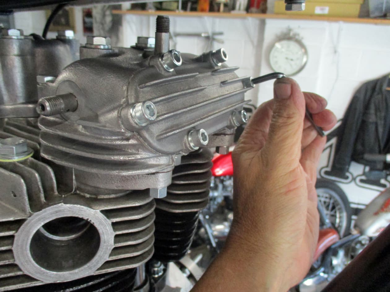
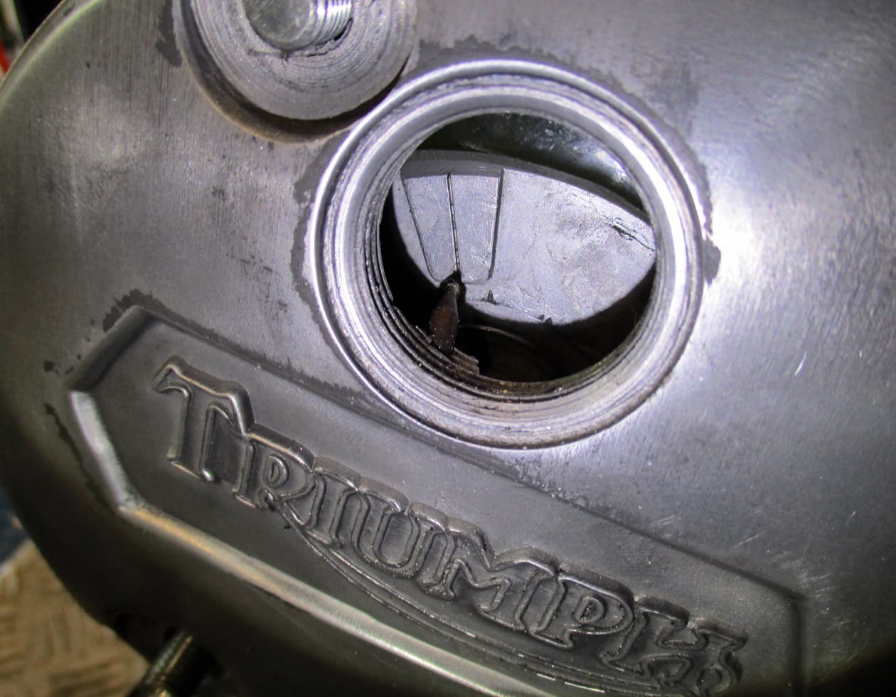
This is looking down the right hand sparkplug hole.
The shiney thing below the screwthread is the inlet valve in it’s open position (that’s when it’s letting the fuel/air mixture into the combustion chamber)
The engine can be kicked over while looking down the sparkplug hole until the inlet valve can be seen, the piston is then on it’s compression stroke.

The engine is put into 1st or 2nd gear.
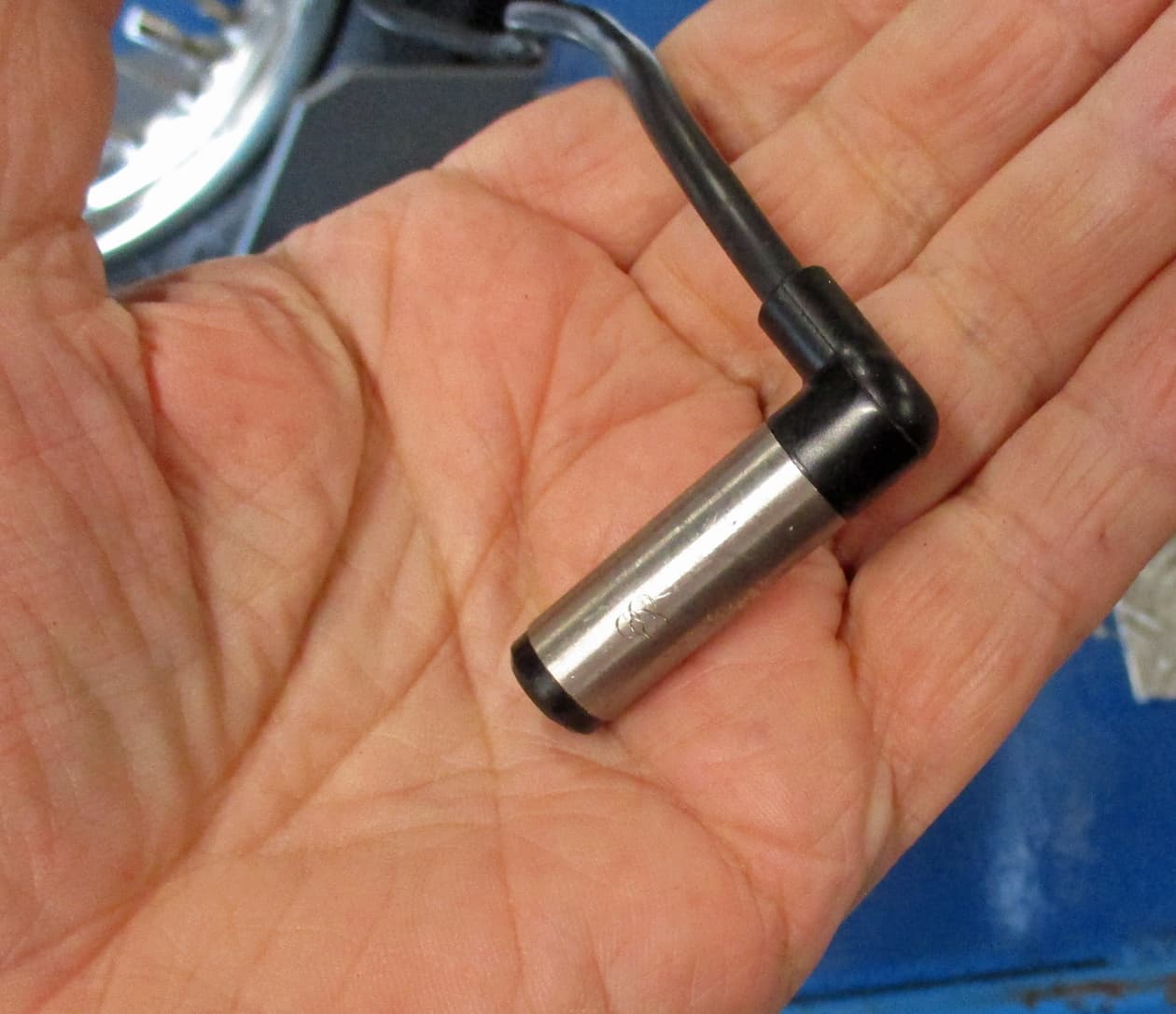
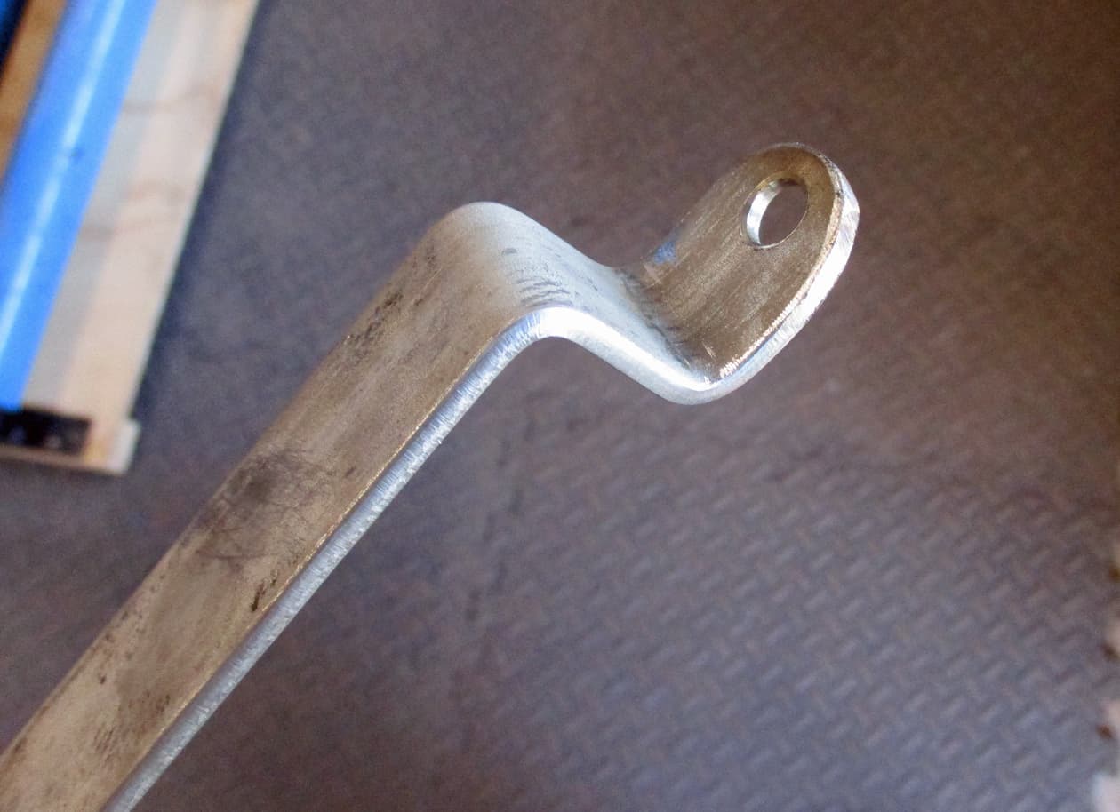
A long thin thing can be held down the sparkplug hole to feel for the top of the piston (I do have a long thin stick for this but I seem to have lost it).
The engine is turned over by moving the back wheel as though the bike was moving forwards therfore turning the engine over as it would when running. Note the T140 engine normally runs clockwise.
The piston will move upwards, do this slowly as the long stick thing will get jammed if you are not careful.
Feel for when the piston is at it’s highest, move the wheel forwards and backwards to feel for piston movement. This method finds TDC pretty accurately - better than those screw in measuring stick things.

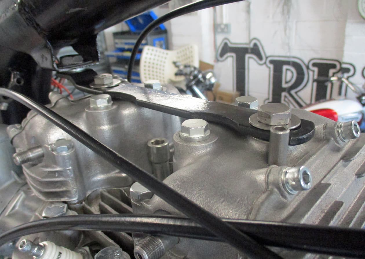
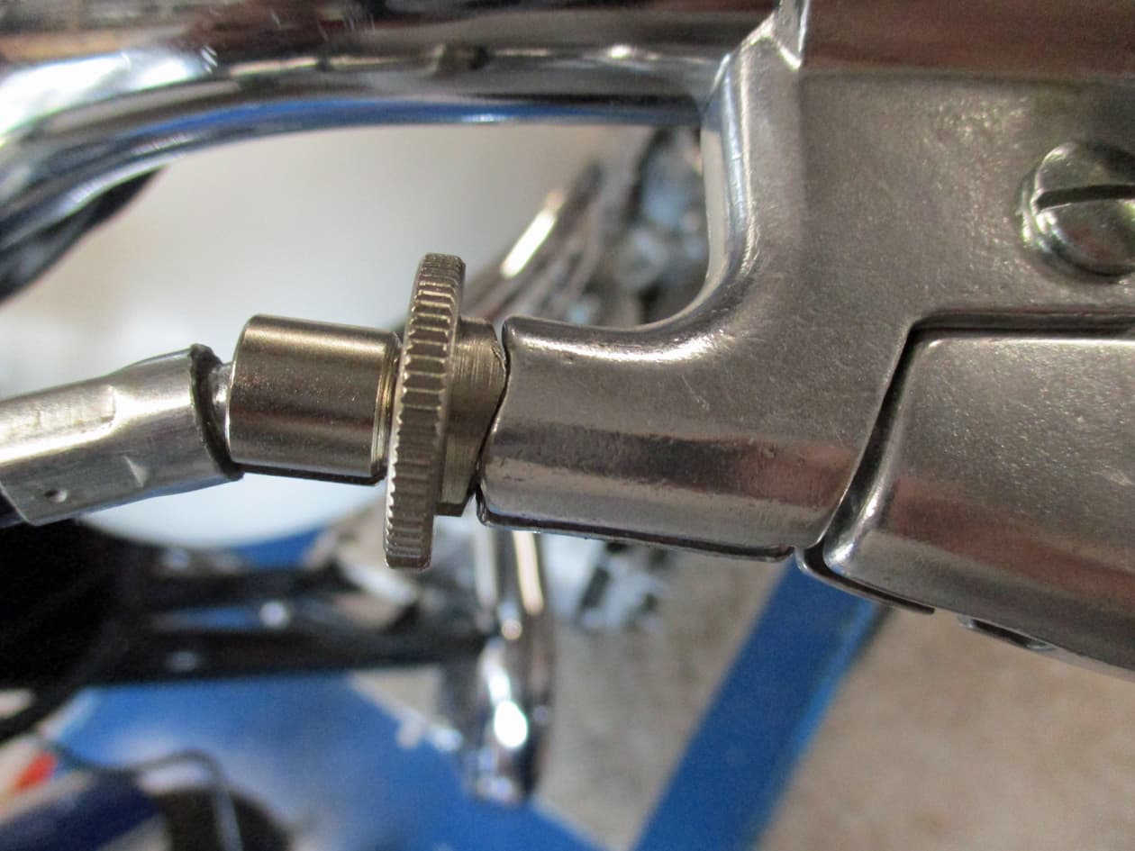
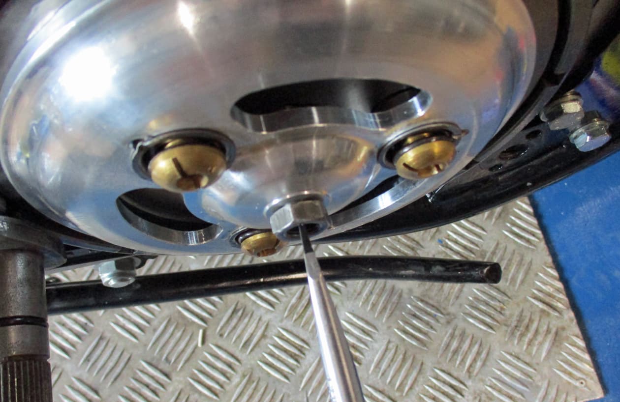
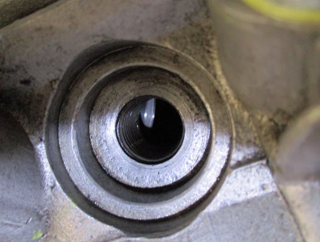
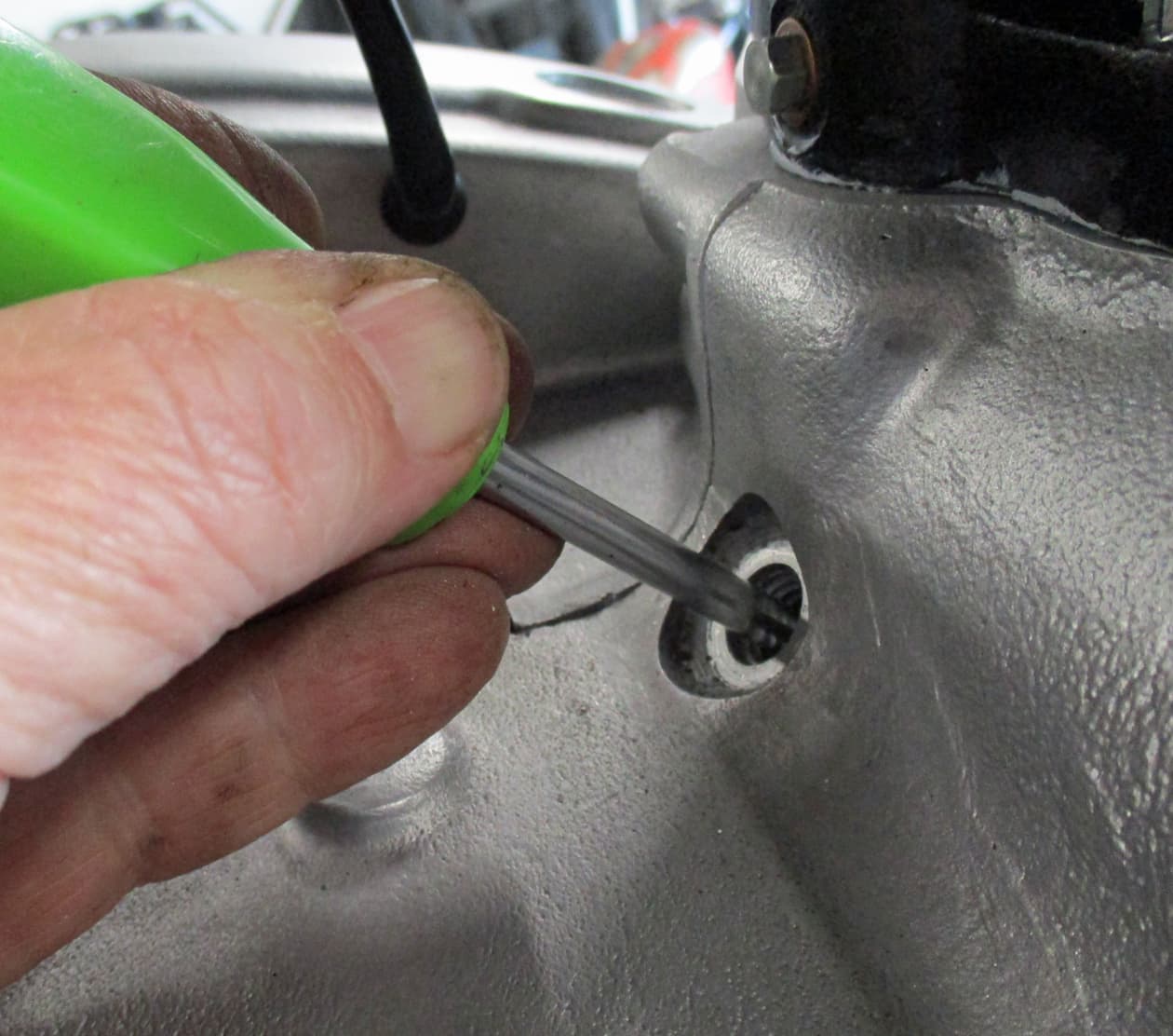
Stick another feeler thing (not your finger as it’ll get stuck) this is a posidrive screwdriver into the timing hole in the crankcase. Feel for the flat of the crankshaft flywheel. Move the back wheel again fowards and backwards until the feeler feels the slot in the crank.
Try the level of the piston again.
The engine is now at TDC.

We’re looking to find 38 degrees Before TDC. This is where we’ll tell the engine to fire using it’s electronic stator plate (points).
Move the wheel backwards. This moves the engine backwards as we want BEFORE TDC. The ignition has to start BEFORE the piston gets to it’s highest point to allow time for the fuel to burn.
Sorry about the shouting but it’s easy to get confused.
So, move the wheel backwards in little hits while feeling the flywheel/crankshaft move under the feeler in the timing hole. Keep going until the feeler slips into the 38 BTDC slot.
The engine is now where it’s needed to be to set the ignition timing.

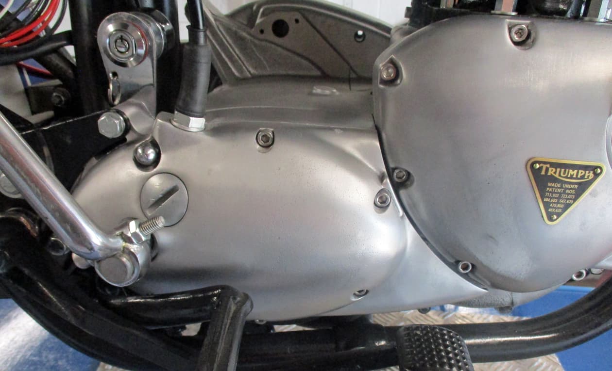
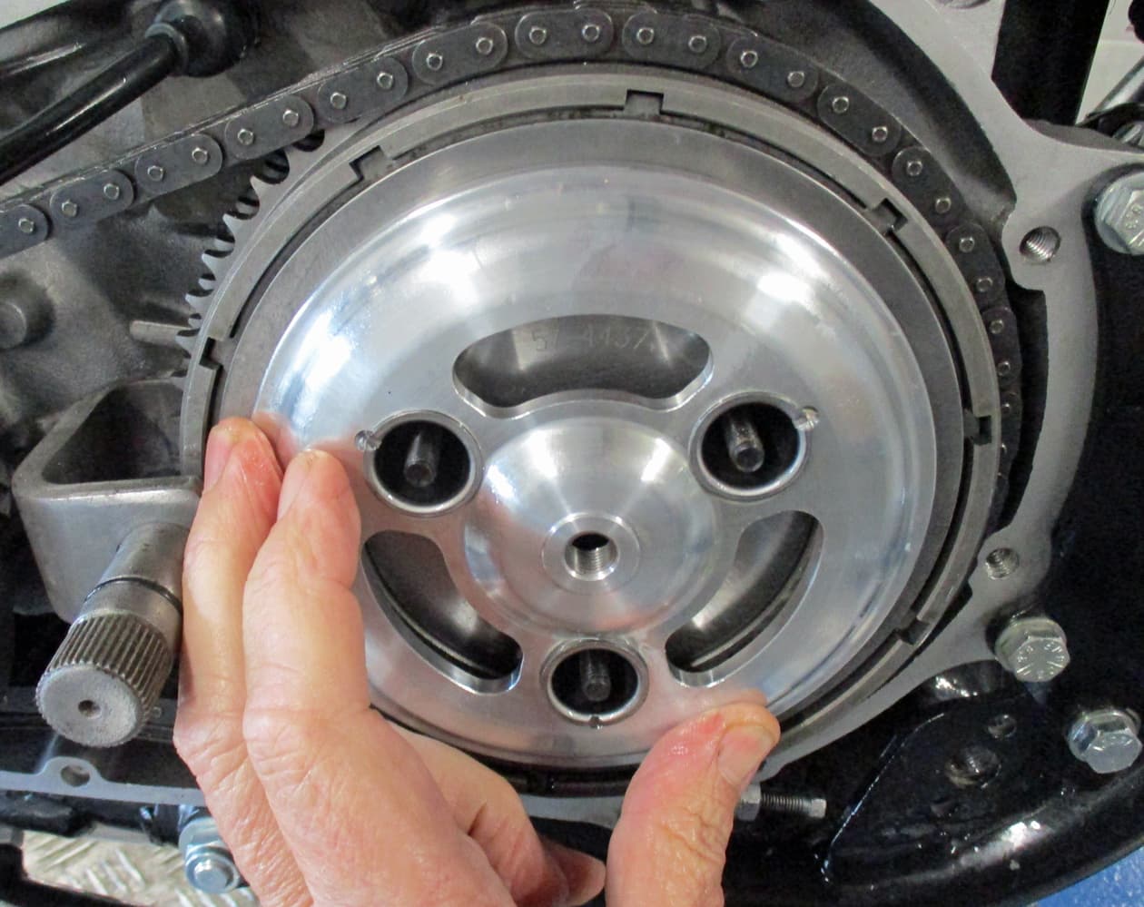
On left hand gear change T140s there’s a little opening in the primary cover with a pointer. The pointer will be at the timing mark on the rotor. Here it’s spotty dog right on the mark.
I just temporarily slotted the primary cover on for this.
These will be marks used when strobe timing once the bike is running.

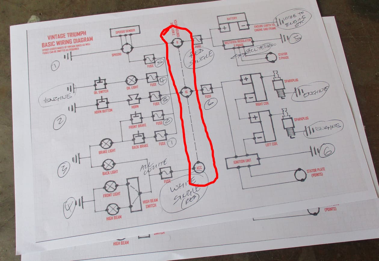
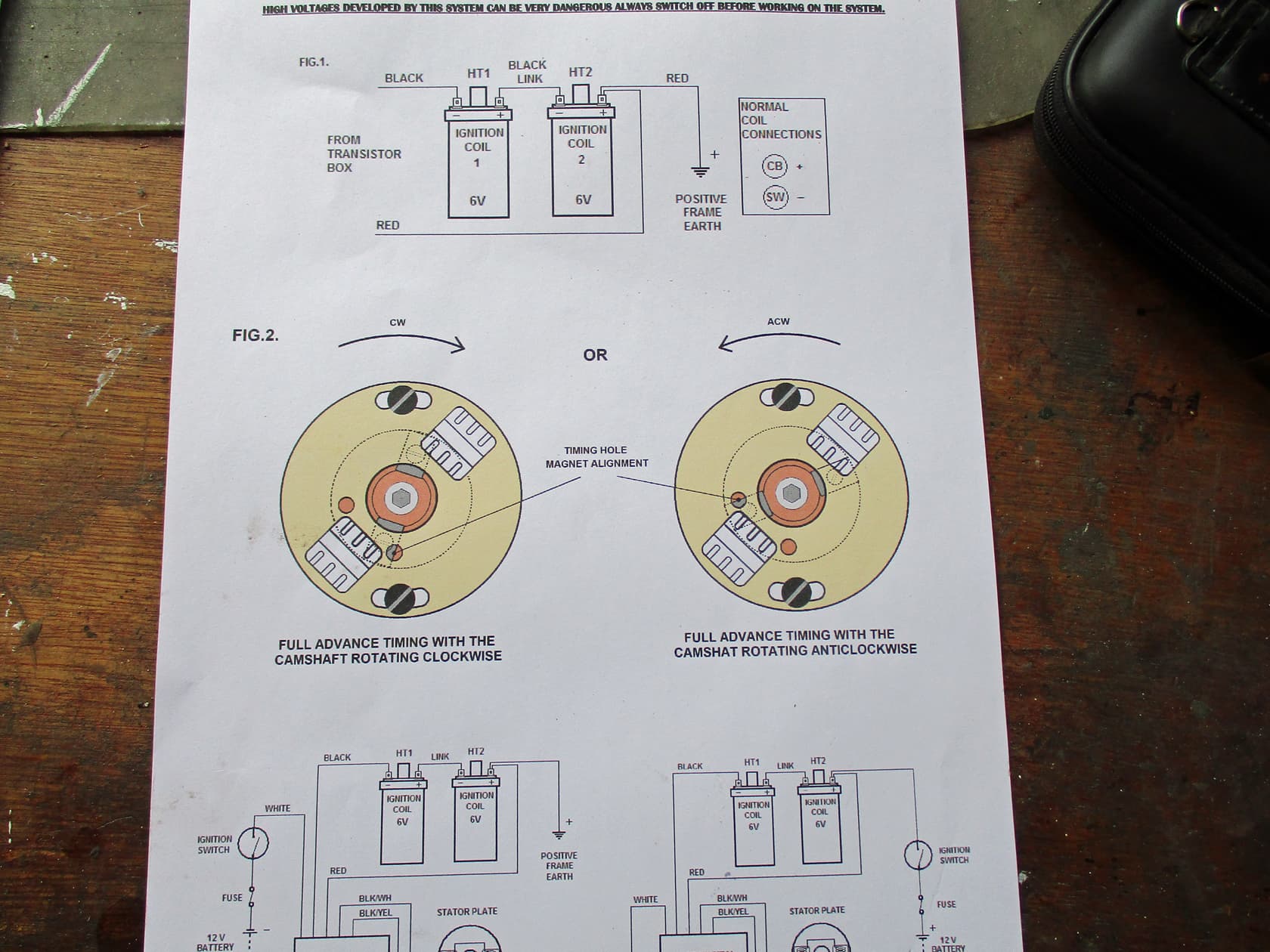
I downloaded the instructions for the Boyer Branson unit. There’s a long list of each model available on their website.
Note there’s a difference for clockwise or anti-clockwise running engines. Horrible BSAs and Nortons run that way for some stupid reason.

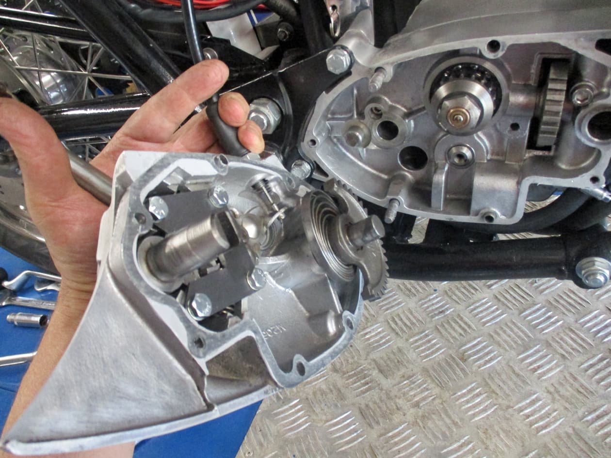
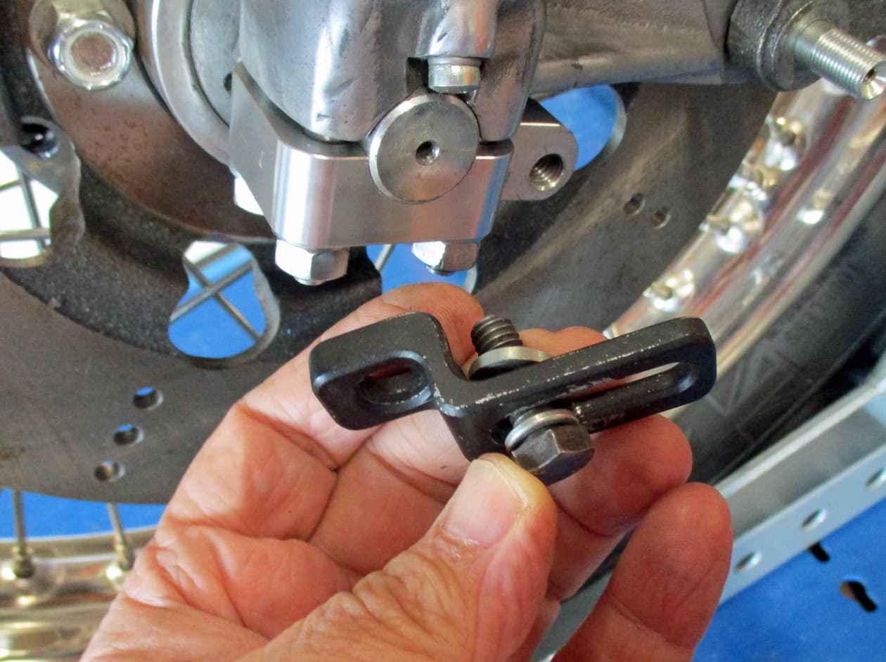
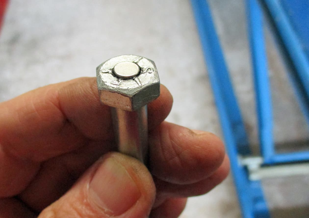
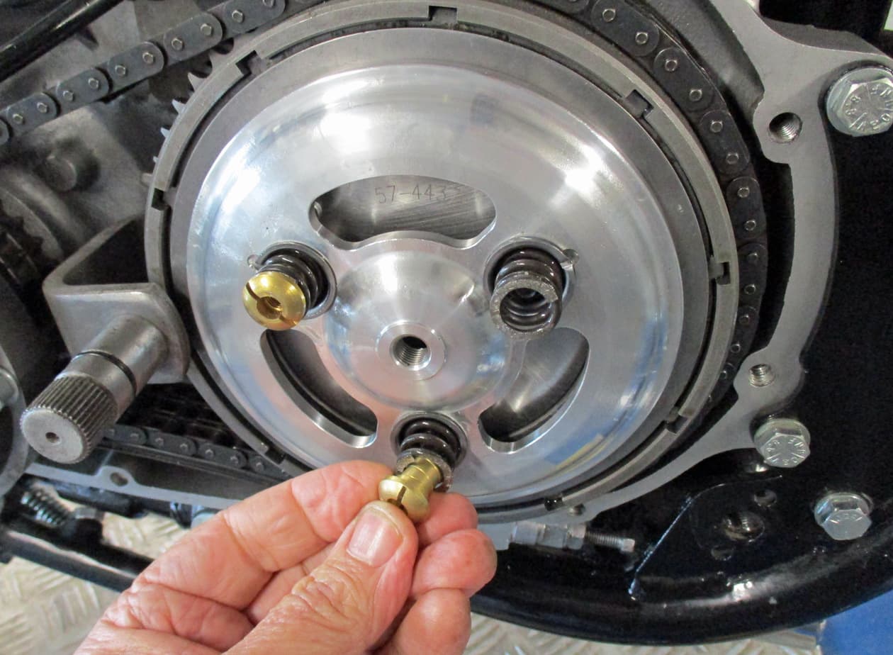
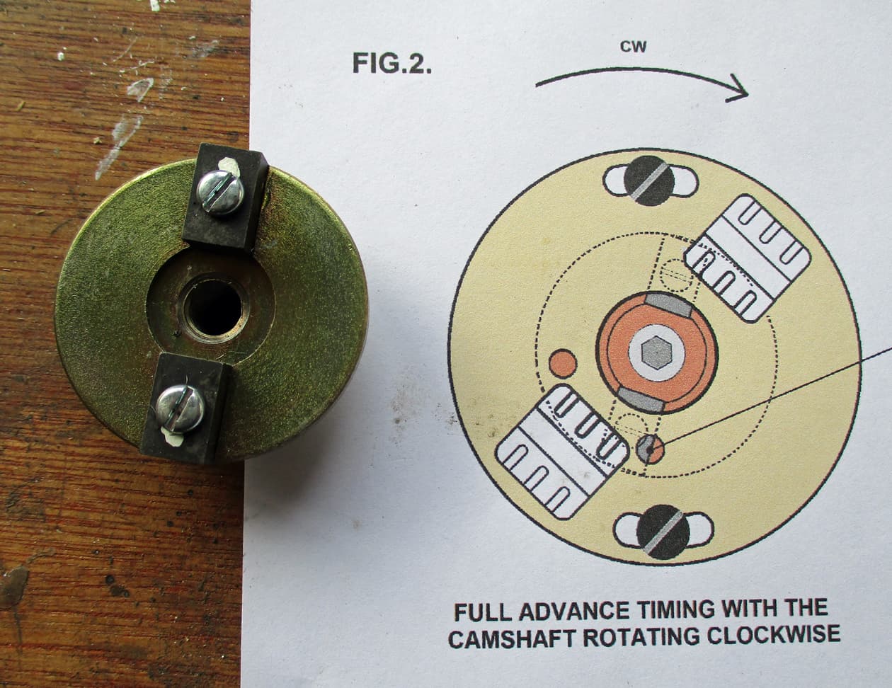
Here’s the moving plate with magnets and it’s correct position on the diagram. I think someone had painted little white dots on the magnets already. Although I don’t think they are needed looking at the instructions.

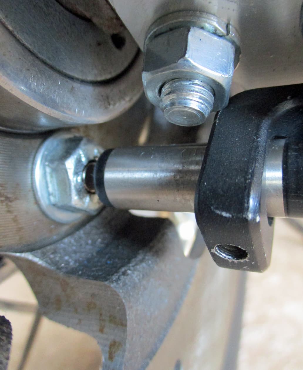
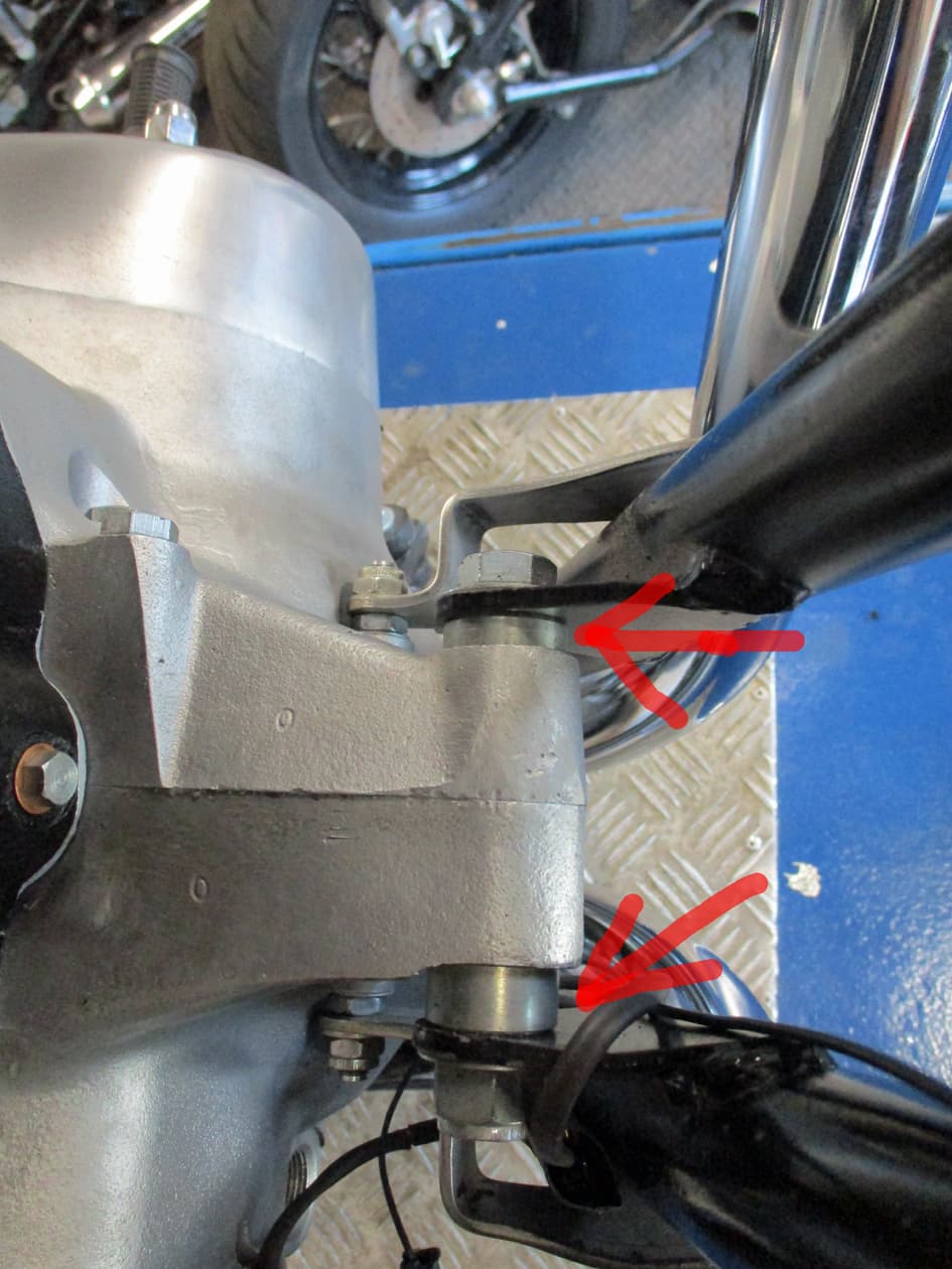
The plate is lightly screwed into the end of the exhaust cam so it can be moved to set it correctly once the front plate is positioned and secured.
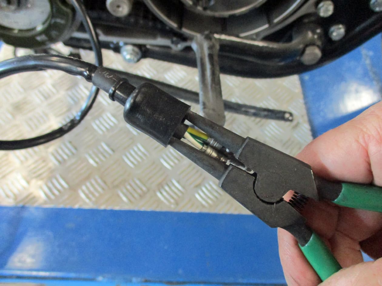
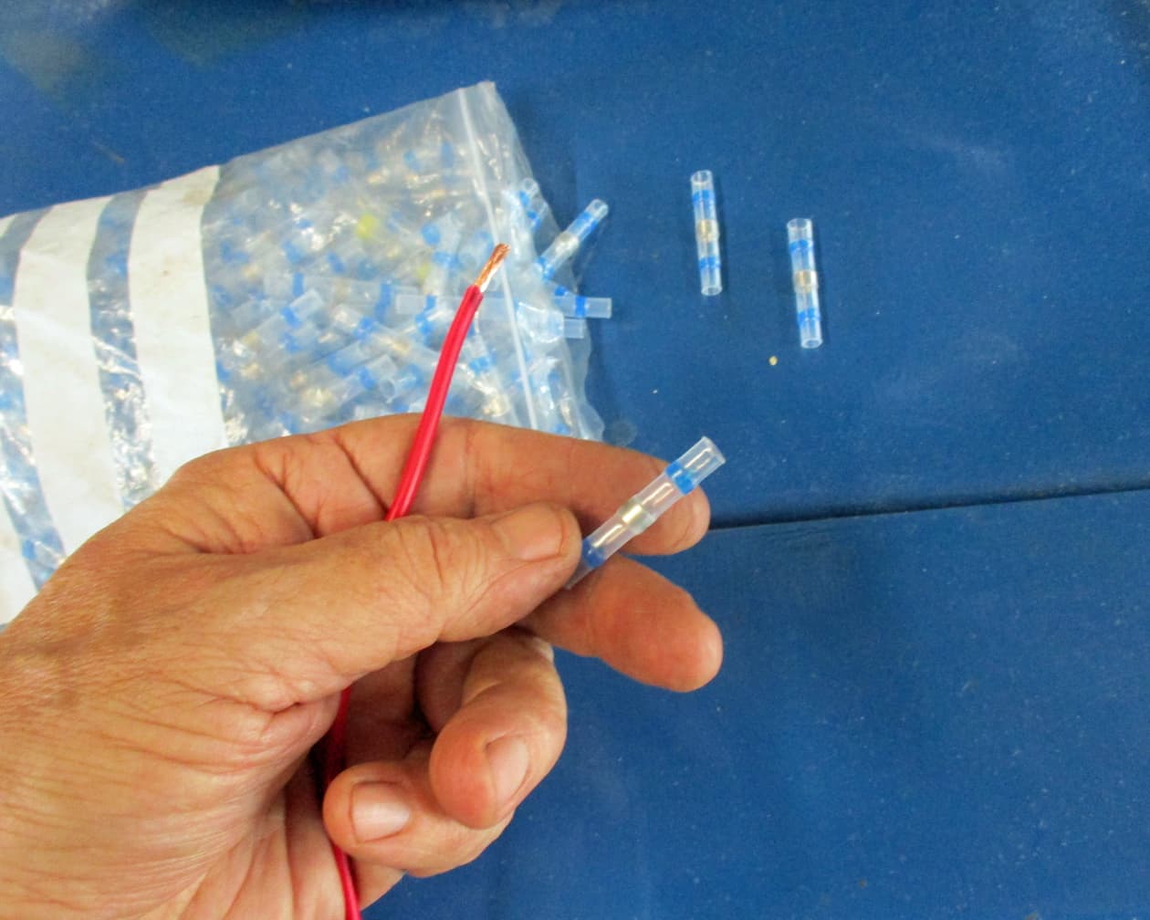
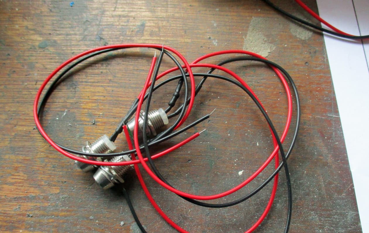
I didn’t like how the bullet connectors were made to be under the points cover. So I duely cut them off and soldered extra lengths onto the two wires so the connections can be outside where I can see them. I’d like to easily check if they’ve come disconnected if the bike conks out.

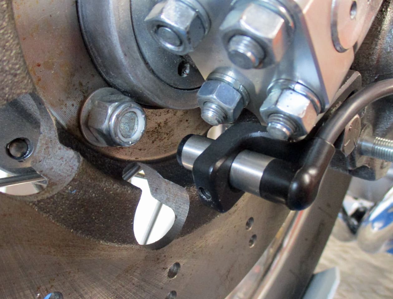
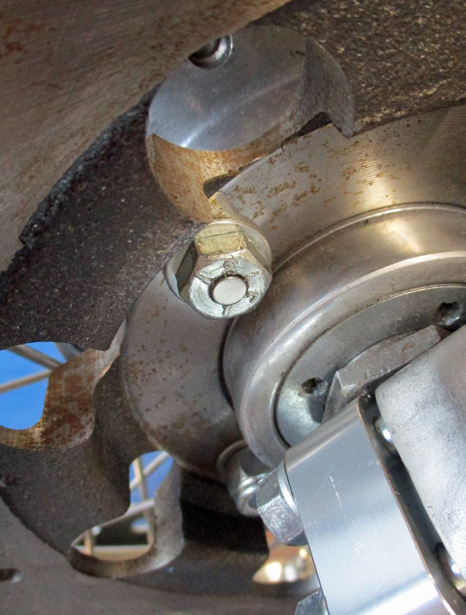
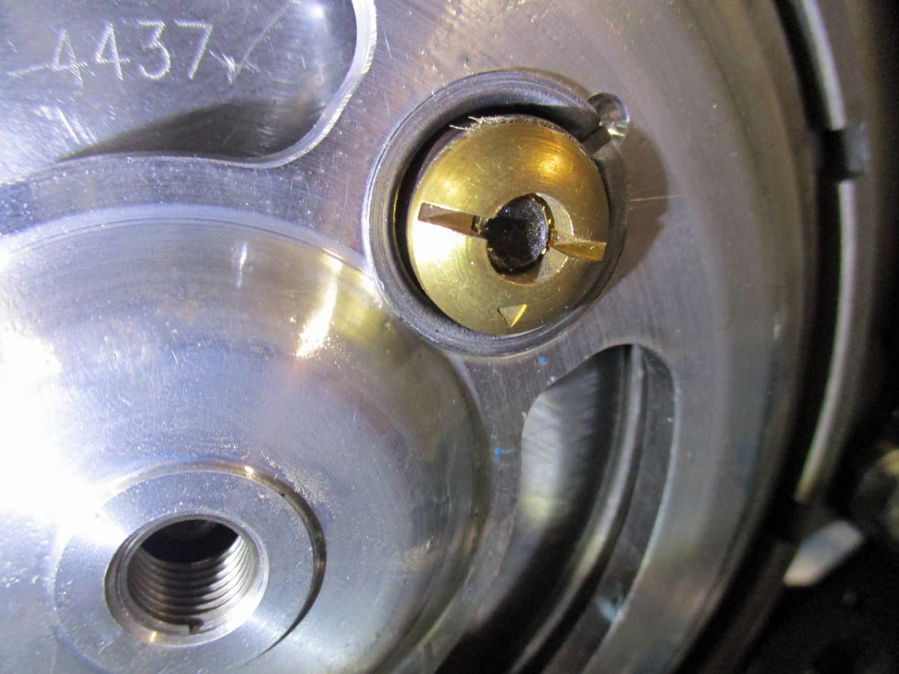
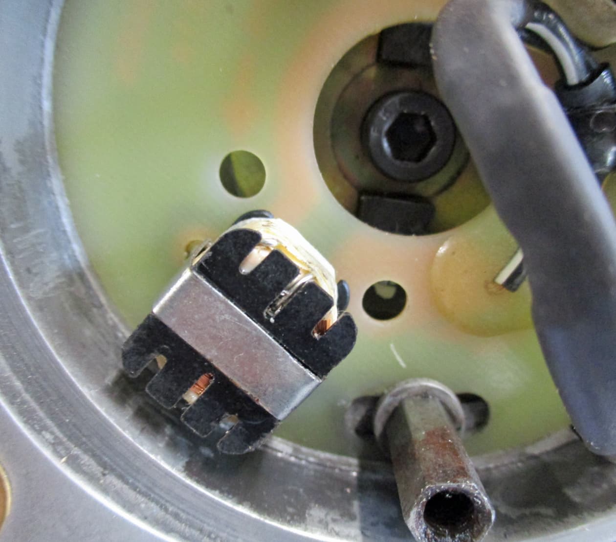
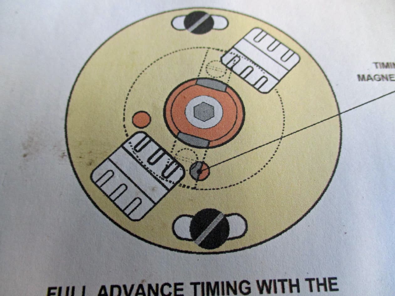
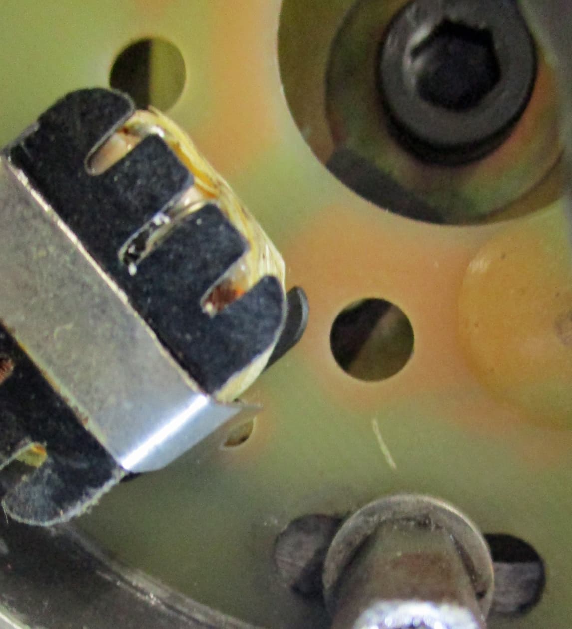
Here’s the stator plate with the white dot on the magnet peeking through the ‘clockwise hole’. I’ve no idea why that’s printed on the back where it can’t be seen.

But the instructions show that the magnet’s edge should be halfway through the hole. There’s no sign of a white paint dot.

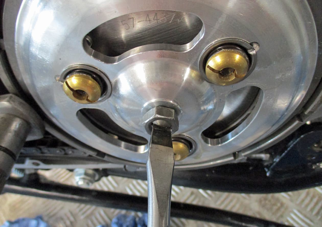
So, that’s where I’ve set it. I’ve no idea if it should be the white dot or as the instructions show but I’ll go with the instructions. Tighten up the bolts.
If the bike runs but the timing is a bit off it’ll be fairly easy to sort by slackening off the pillar bolts and moving the plate.

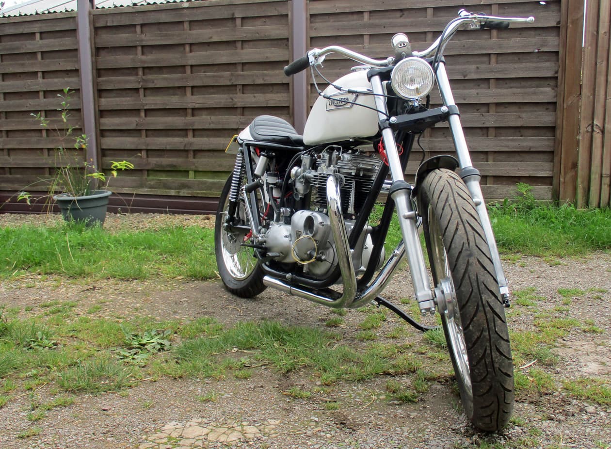
So, that’s that. Ignition timing should done so found a groovy points cover and put that on.

11 Likes

Well, that’s not the end of the ignition timing story. Oh no.

So, I thought, It’s all wired up, I should be able to turn it on, kick it over and check that there’s a spark.
I was so happy that I’d completed another pesky wiring job that I asked the admin Staff to come and witness my greatness in all things Triumphness.

Pulled some HT leads and caps from a bike waiting in line. Connected those up to the coils and sparkplugs. Positioned the sparkplugs so the sparks could be seen.
And, for the first time since 1983, (that’s 40 years in my reckoning) I switched it on and kicked it over to marvel at no sparks at all. Bugger.
Play with the HT leads, check that the lights work, check that the battery has enough voltage in it. The Boyers have a reputation for needing lots of volts to fire.
Press the hooter a few times to wake everybody, and the bike, up.
Reposition the sparkplugs and kick again a few times.
Nothing. Bolloxy bumholes.
Tidied up, locked up and went in to make a cup of tea with the hump. :face_with_symbols_over_mouth:

Got halfway through the tea and…Bloody 'ell, Just remembered.
I’ve wired in an ignition secret on and off switch!!!

Unlocked everything, turned on the ignition key, switched the secret switch under the seat and…hey, presto! kicking it over produced lovely big blue sparks.
That bloody cheered me up :stuck_out_tongue_closed_eyes:
I’ll sleep better tonight…phew…thank you…over…

4 Likes

The things to do and parts lists are getting noticably shorter :slightly_smiling_face:
One of the fiddly bits is to make up some brackets for the zorsts.

These engines are spaced differently on each side so the brackets to fit and fix the zorsts are slightly different. As I’ve put the larger diameter TT pipes on this there’s no standard brackets available so out with the stainless.

And bend, drill, bend, bend, fiddle, bend, bend etc you get the picture

Then start another for the other side

Done, another item to cross off…wlecome… :neutral_face:

9 Likes