T140e 1980

The less paid for the project bike, the greater the pile of spares required. But as labour is free the overall cost, purely in pound notes, is less.
Swings and roudabouts I suppose :expressionless:

New discs required I think

Onto the back wheel. Find the correct positioning of the spokes holes and temporarily bolt up. New bits and bobs for the disc side. Took a while to figure out the correct pieces as this has 1985 parts according to the parts catalogue.
Sometimes the parts catalogues can be quite misleading as a PO may have worked on the bike and mixed bits up from differing models and years. A set of all years model parts books is well handy for trying to figure things out.

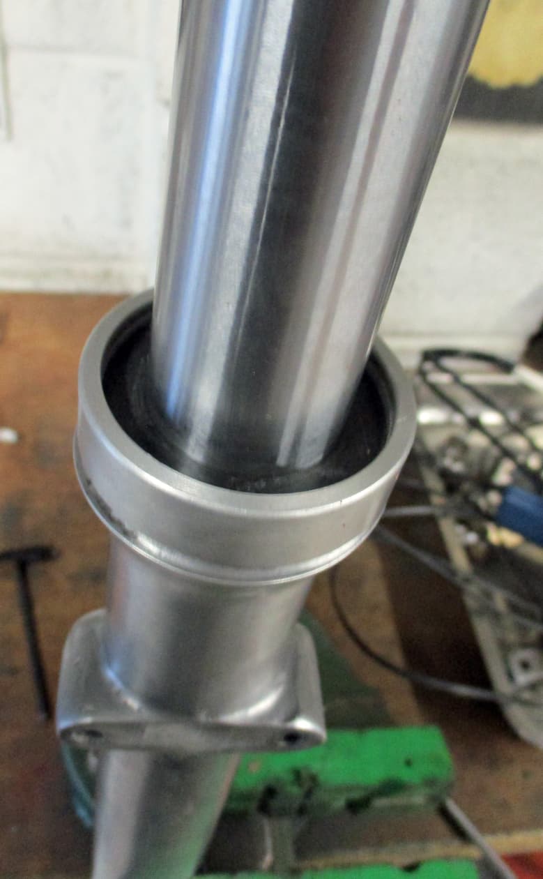
Press the bearing on in the vice…

use a suitable drift to knock it on the rest of the way

listen for a change in tone when bashing to tell that it’s seated.

Assemble all as shown in the parts catalogue. Careful when bashing in the bearing onto the dust cover as it’s too easy to break the ally stop off inside the hub. Keep looking to ensure the dust cover isn’t going to rattle.

Nip up the left hand thread locking ring. No need to overdo it.

Long spacer goes in the other side and assemble the rest

Lastly push in the dust cover.

Then onto the wheel building.
Slightly different than the front as the rim’s centreline is pushed to the right of the hub so that the chain doesn’t rub on the tyre.
So to enable this the spokes are bent slightly differently and are different lengths. Dealers should supply the spokes as a set and clearly labelled.
Typically, mine were not as there was limited availability when I wanted them so it took a bit of fiddling and farting about to sort.

Build the spokes in exactly the same way as the front wheel above. Ensure the outer spokes now point in the direction of rotation so the massive acceleration forces from the mighty T140 engine are suitably provided for.
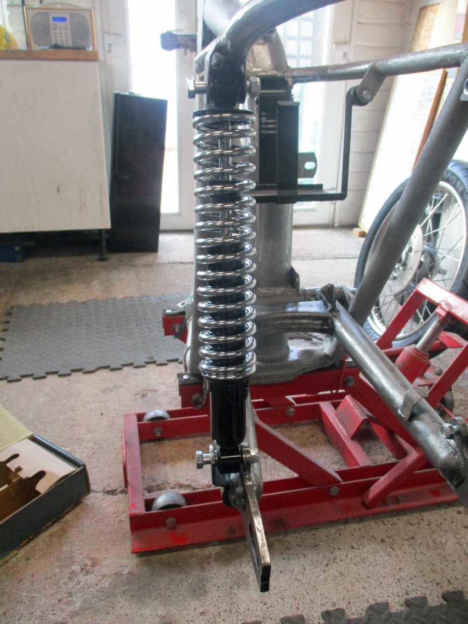
The stand has to be adjusted and it’s spindle can be used this time as there’s no axle through the wheel.

14 Likes

Wow thanks for the commentary re the spokes. I understood right up until the point where you started to work on the alignment of the rim. at that point I think it’s one of those things I would learn better from someone in the flesh to save me screwing it up. Fortunately I don’t need to play with my spokes at the moment.
Epic thread and very fascinating.

3 Likes

One of those jobs that takes a bit longer than you think to get right

Swingarm brass bushes pressed in using long bolt and a couple of large washers. These need to be reamed out straight to ensure alignment to allow the bobbins and the spindle to slide in. It can be done using a bar wrapped in emery cloth and sanding carefully until everything fits as it should but a 1 inch diameter long reamer (to align through both sides at once) makes it an easier task and ensures no movement or slack in the spindle once it’s tightened up.
Grease nipples and greasing will wait until painting done.

All threaded holes need to cleaned out using a tap. Particularly blind holes as they hold old gasket compound and any blasting medium. Surprising how much is sometimes in them, especially on engine cases.

Double nut install the nice new studs into the bottom of the fork sliders. Just nipped up, no need for strength here.

All in, luvly.

New abutments and races installed into the frame headstock. The abutments just press in but the races have to be drifted in with a correct size tool so it goes in square. The cheap set of bearing drifts has just the right size - 44.5 mm I think it was.

Bottom bearing is pushed onto the bottom yoke spindle, well greased and fed into the headstock. The top bearing is pushed in…

and the dust cap and top yoke is placed on. The headstock top nut is then screwed in. The nut will slip through the top yoke and place pressure onto the top bearing and pulling on the bottom bearing. This forces the bearings into the races. It is not there to put pressure onto the top yoke, the top yoke is held by the nice new pinch bolt onto the top nut. Once the forks are inserted it will be held straight with the bottom yoke…over :slightly_smiling_face:

10 Likes

Onto the forks due to the arrival of more spares

Existing slider and damper tube that were both ok after a clean up but everything else new. UK manufactured stanchions - a bit dearer but better quality

Change o ring on damper valve (these are always worn even if they don’t look it)

Insert damper into stanchion - ensure it’s the bottom end

and screw in end plug.

Looking down the slider (see how nice and clean it is now?) there’s a recess around the hole for the dowty washer.

Chuck the washer in and waggle the slider about until the washer sits flat in the recess.

Carefully (so as to not move the dowty washer out of the recess) put the slider vertical in the vice. And even more carefully slide the stanchion - with the damper rod sticking out the bottom - into the slider.
Push the stanchion down until it feels like the damper rod is on top of that dowty washer in there.

This is looking up from underneath the vice. Thread the allen bolt up from underneath to screw into the bottom of the damper, just a few threads in is fine. No need to be tight, just enough to hold for now.

Lay the whole lot on it’s side in the vice and assemble the long extensions and suitable socket to hold the top nut on the damper valve.

While holding the damper with the extension screw up the allen bolt tight. Also screw in the drain plug washer and screw.

Put the whole thing vertical in the vice and insert the nice new oil seal

Push it down passed the groove for the circlip using a drift to tap around the circumference of the seal. Just tap it in gently.

Insert the nice new metal retainer

And then the nice new circlip…

… making sure it’s in the groove man.

Whack on the scraper sleeve/cover

Thread in the fork main spring

And using that well handy palm ratchet, push down and screw in the top nut.

Sorted. Just the other one to do and it’ll be a pair :sunglasses: cheers…over

10 Likes

Iron.
This is so so interesting. Yes you should write a book on the whole project.
Joe.

1 Like

Bunji corded the frame to the bike lift so it’s a bit easier to fit things on.

Notice the preloved battery tray fitted - I’ll make some coil holders when I get to that bit.

Hold up the swing arm into position and note the spacer gaps each side. There’s a thick one and a thin one.

Slot the thick one in and slide the nice new swingarm pivot bolt in. Note there’s no grease nipples or rubber covers yet as it’s just the dry build.

Slot the thin spacer in and push the pivot bolt all the way through and thread the washer and nut on. No movement at all in the swingarm with the new bobbins and bushes it there.

Nice new shocks

Slot the bottom and then the top bolts through

All looks good. Still not sure about the subframe loop but as it’s been off and then welded back on already I’ll wait until I start the seat body work.

Threadle the rebuilt fork in - no oil in as yet, dry build and all that.

Do up the pinch bolt to hold.

Threadle in the other side, etc.

Looks a bit more like a bike now.

Replaced the yoke nut with an older version from the stash. The newer one was to save money I suppose when originally built at the factory but even with the plastic cover on it isn’t nice. The older version needs to be trimmed down and tapered a touch as it’s about an eight of an inch too long.

Looks loads better. Again, still unsure about those ‘ears’ on the top yoke that the clock’s tray bolted to. They may be used but probably will be ground off.

Used the old c clamps to stick on some old drag bars so I can move the bike around once it’s got wheels on.

10 Likes

All luvly looking front on

New kickstand spring on. No need to strain getting the spring on, loop both ends of the spring on without the bolt in, then use the stand as a lever to align hole and stick the bolt through. It’ll need a new nut. These later kickstands have an extra long toe piece which looks a bit silly. There’s no adjustment bolt so that may need to be drilled and threaded to install one. I’ll wait to see what it looks like later before commiting to that.

Back wheel on and sort of spaced to centre line of bike. I’m leaving off the speedo drive as it’s seized solid and I’m using an electronic one driven by the front wheel.
Using some temporary spacers to centralise the rim for now until I get the engine in and can align the front and back sprockets as the chain needs to run straight. I’ll then measure and make up some spacers.

The Admin Staff went shopping and got me these. Triff, they’ll be stuck on the bikes somewhere I expect :grin:

Here it is on it’s feet. Now to decide on the rear end design. So been musing holding up mudguards, loop at all angles, leaving the loop off, different back lights, number plate, different seats, :thinking:

13 Likes

Right, had a muse, and decided to put the loop back on

Trimmed nicely at, sort of, the angle that i thought looks best.

Cut some slugs of steel bar to hold the sub frame parts together. Note the hole in the frame where one of those studs came out of that stuck in me many moons ago

Rather than trying to bend with fire and a massive hammer (as getting the angle would be a bit of an issue) cut a pie slice out

Bend it over

and weld them up after giving them a bit of a grind to remove the oxidation

Drill some, handy to get to, holes to weld through the frame onto the slugs. Tack weld the slugs so they don’t move around.

And weld it all up. A bit of grinding to make good

Parked up while I have a tidy up and a think about the next step on seat base/cowl building. Thankyou…over :slightly_smiling_face:

13 Likes

In one of those ‘can’t think what to do’ stages that seem to go with most builds. Sat drinking tea pondering. I was going to go the Sunny Nutter route and not include a back mudguard. However, we don’t live in sunny California so decided to mount one to save the electrics etc from spray and all sorts of other unmentionables.

I cut and welded a sort of semi circle piece to the inside of the tail loop

then cut, bent and drilled a stainless bracket for the bottom of a standard mudguard. That stainless is a right arse to drill. It’s gotta be kept as cool as posible as it’ll heat up, harden and then be a real whatsit to drill, guess what route I took…buggered drill bits now need a resharpen.

Roughly cut a mudguard (it’ll be repainted etc) from the stash and bolted it on loosely. Plan is to cut it around the loop so it’s not easily seen but is there to protect the electrickery. Over…

9 Likes

Continuing with the seat. This all may end in tears as I’m not really sure what I’m doing with this. But if it doesn’t work I can always start over or just adjust a standard one to fit.

Cut a seat base to fit the subframe. The mudguard is a bit higher so I cut a rough hole to suit. I may have to cut another one for coil/battery access but let’s see how far I get with this first.

After playing with a piece of card on the seat base for a cowl. I cut a similar sized piece…

…and bent it over a piece of tubing by hand…

…until it, sort of, sat ok and married up, ok-ish, on the seat base.

Luckily, in the nick of time, the postman brought some handlebars etc. So I could leap into action on something I have a bit of an idea what I’m doing.
Triumph had this obsession with vibration, believing that they were losing orders due to riders getting the hump getting white finger syndrome. So they mounted the handlebars on rubber mounts. Rubber mounted handlebars are just rubbish so they have to come out.

8 Likes

I like the lines of that seat so far., and that metallic finish as it appears in the photo. I don’t suppoese that’s the final look but still. :slight_smile:

2 Likes

I agree with @Octoberon. The lines on the seat look great to me and I’d stick with it (sounds too easy doesn’t it…)

2 Likes

Sorry, had to rush off a bit sharpish and then eating needed to be completed. :slightly_smiling_face:
Yes, thanks, hopefully the seat will come out ok. Fingers crossed. Gotta try something new otherwise it’d be boring.

The rubber mounts had been rusted in so the outside tube needed to be cut to get out.

A bit fiddly but got that one in the end

i couldn’t even hammer the left one out without the stanchion coming up through the yoke so got the drill out, that’ll show it!

Here’s the solid mounts that fit stright into the yoke. I really could do with a lathe so I can make my own things like this.

They tap straight in, top and bottom.

New fiddly spacers/packers for the nice new Western handlebars

All bolted up but need some new spacers for the pinch bolts.

I nearly packed up then as I was a bit aprehensive continuing with the seat base welding but hey ho, hold it all in the vice and get the blimmin’ welder out you wuss…

As it’s thin steel sheet the welding is basically spot welding on a lowest heat. Leaving a space then another spot weld. Penetration looks ok and I actually didn’t blow any holes and it all looked really scruffy but ok.

So, carried on and welded up the inside, then cut to where I thought the cowl looked ok and ta da…bloody hell, not bad at all. But let’s see when I weld the seat part on and get the grinder out. Who knows what will happen in the next episode, thank you…over :slightly_smiling_face:

9 Likes

Looking good!

Blimmin’ well bully me! Didn’t do much today as other “being old” stuff is getting in the way.

Did some grinding on the welds and will you bloody well look at that! Fuck me, I thought it was gonna look like a dog’s dinner.

On the back and lookin’ the dogs bloody nuts even if I say so myself :grin:

Bunged an old tank on and sat back with a tea. Come on, how fuckin good is that welding?!! (Best not bugger it up now when I weld the other bits on…) Chuffed or what…over :sunglasses:

8 Likes

Evil knievel replica paint job? It’ll fetch an extra grand.

It’s….

1 Like

Yesssss, well, lovely :neutral_face:

Cut out a closing piece and bend to suit

Stitch weld it into place

Connect the stitches together with more stitch welds and grind them all down. This takes a lot longer than it looks. Still a bit of welding and tidying up to do.
But now trying to figure out how to actually turn this into a seat :thinking:

12 Likes

Now how to turn it into a seat. As with chop builds, one requires a seat pan…I think…

So, find a piece of sheet steel (I’d already got an alluminium sheet out of the stash when I realised I will have to weld bolts to it so I put that away (but not until after I’d cut it - bugger)).

Cut it to an appropriate size (I’d had practice so it was easy to do) and bend accordingly over one’s knee

Cut again to the base size then try to figure out what the next thing is to do.

I drilled many, many holes put in many, many bolts and finally figured that I didn’t really want to sit on protuding nuts and bolts. So welded threaded studs onto the bottom of the seat pan so it bolts down onto the seat base. I’ve cut and pressed on rubber edge stuff for now. Once I’ve figured it all out I’ll paint the base and stick it on permanently.

I was so excited that I’d come up with this solution (ok it looks simple now but it wasn’t when I hadn’t thought of it) and there was some dicky know all on the radio I actually welded two of the studs onto the wrong side. So they had to be cut off and welded back on.
I’ve ground down the welds a bit figuring that the seat foam spongy stuff will stop them digging into one’s bum cheeks.
Some Admin Staff assistance required now I think for the seat covering but I’ve ordered some upholstery foam all on my own. Thank you…over :no_mouth:

10 Likes

Well, I for one think you’re very clever. Great work!

2 Likes